Variable Control and Applications of Piston Hydraulic Pumps (Motors).
A comprehensive guide to the principles, control methods, and industrial applications of piston hydraulic pumps and motors. This resource covers everything from basic concepts to advanced variable control techniques.
1. Basic Concepts(Hydraulic Pump Motor)
Understanding the fundamental principles of hydraulic systems and components is essential for mastering piston pump and hydraulic motor technology.
Hydraulic Power Transmission
Hydraulic systems utilize Pascal's Law, which states that pressure applied to an enclosed fluid is transmitted equally in all directions. This principle allows hydraulic systems to transmit power efficiently over long distances and around obstacles.
The basic components of a hydraulic system include a pump, hydraulic motor, valves, actuators, and hydraulic fluid. These components work together to convert mechanical energy into hydraulic energy and back again.
Key Hydraulic Parameters
- Pressure: Measured in pascals (Pa) or bar, pressure is the force per unit area exerted by the hydraulic fluid.
- Flow Rate: The volume of fluid passing through a point in the system per unit time, typically measured in liters per minute (L/min).
- Power: The rate at which work is done, calculated as the product of pressure and flow rate.
- Efficiency: The ratio of output power to input power, accounting for losses due to friction, leakage, and heat.
Piston Pumps vs. Other Pump Types
Piston pumps are distinguished from gear and vane pumps by their ability to generate high pressures (up to 700 bar) and their variable displacement capabilities. This makes them ideal for applications requiring precise control and high power density.
Hydraulic Pressure Basics
Pressure in hydraulic systems is created by resistance to flow. The relationship between pressure, flow, and resistance is governed by Ohm's Law for hydraulics: Pressure = Flow × Resistance.
Components of a Hydraulic System
A typical hydraulic system consists of a reservoir, pump, valves, actuators (hydraulic motors or cylinders), and hydraulic fluid. Each component plays a critical role in system performance.
Energy Conversion
Hydraulic pumps convert mechanical energy into hydraulic energy (pressure and flow), while hydraulic motors convert hydraulic energy back into mechanical energy (torque and rotation).
2. Hydraulic Half-Bridge Theory
The hydraulic half-bridge is a fundamental building block in hydraulic control systems, forming the basis for servo and proportional control technologies.kicker motor hydraulic power lift cylinder.
Structure of a Hydraulic Half-Bridge
A hydraulic half-bridge consists of two variable or fixed orifices connected in series between a pressure source and a reservoir. The control element, typically a spool valve, adjusts the flow resistance of one or both orifices to regulate pressure and flow.
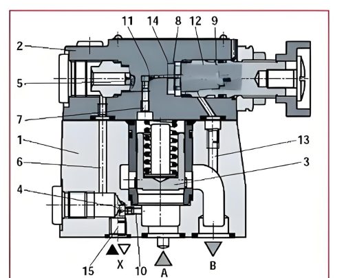
Figure 2-1: Basic Hydraulic Half-Bridge Configuration
Flow and Pressure Characteristics
The relationship between flow, pressure, and orifice area in a hydraulic half-bridge is governed by the orifice equation:
Q = Cd · A · √(2ΔP/ρ)
Where:
- Q = Flow rate
- Cd = Discharge coefficient
- A = Orifice area
- ΔP = Pressure difference across the orifice
- ρ = Fluid density
By varying the orifice area, the flow rate and pressure distribution in the half-bridge can be precisely controlled, forming the basis for hydraulic servo systems.
Hydraulic Servo Valves
Servo valves are sophisticated control elements that use a hydraulic half-bridge configuration to provide precise control of flow and pressure. They typically consist of:
- A torque motor or solenoid for electrical input
- A pilot stage for initial control
- A main stage spool valve for high-power control
Servo valves offer extremely high precision and fast response times, making them ideal for applications requiring accurate control, such as aerospace systems and industrial automation.
Figure 2-2: Typical Hydraulic Servo Valve Structure
Applications of Hydraulic Half-Bridges
Hydraulic half-bridge configurations are used in a wide range of applications, including:
Performance Characteristics
Key performance metrics for hydraulic half-bridge systems include:
| Metric | Description |
|---|---|
| Bandwidth | The frequency range over which the system can effectively respond to input signals |
| Gain | The ratio of output to input signal amplitude |
| Linearity | The degree to which output varies proportionally with input |
| Hysteresis | The difference in output for the same input depending on the direction of change |
3. Working Principles of Piston Hydraulic Pumps (Motors)
Understanding the fundamental operating principles of piston pumps and hydraulic motors is essential for effective system design, maintenance, and troubleshooting.hydraulic engine.
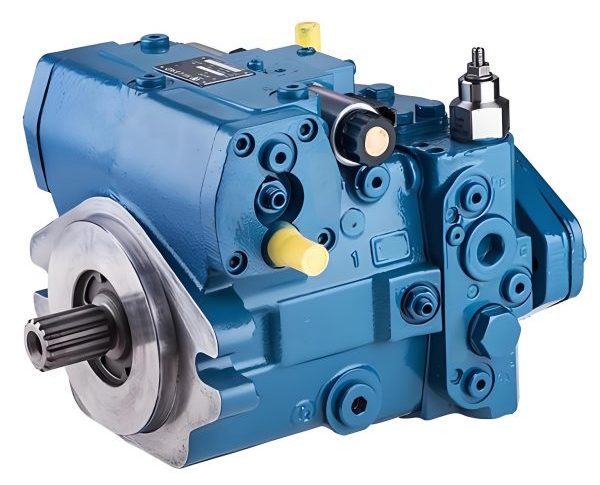
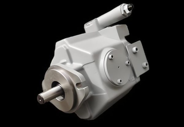
Axial Piston Pumps
Axial piston pumps feature pistons arranged parallel to the drive shaft. They operate on the principle of reciprocating motion within a cylinder block, which rotates around a central axis.
Key Components:
- Cylinder block
- Pistons and shoes
- Swash plate or斜盘
- Valve plate
The angle of the swash plate determines the stroke length of the pistons, controlling the pump's displacement and output flow.
Radial Piston Pumps
Radial piston pumps have pistons arranged radially around a central drive shaft. As the shaft rotates, an eccentric cam or ring causes the pistons to reciprocate within their cylinders.
Key Components:
- Central drive shaft
- Radially arranged pistons
- Eccentric cam or ring
- Suction and discharge ports
Radial piston pumps are known for their high pressure capabilities and precision, making them suitable for specialized applications.
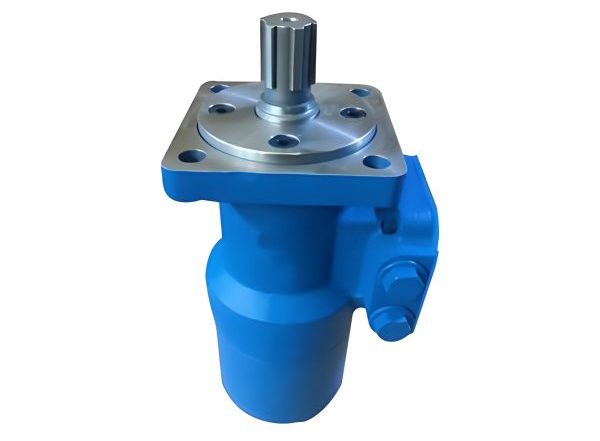
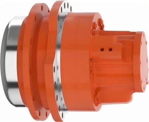
Hydraulic Motors
Hydraulic motors are the inverse of pumps, converting hydraulic energy into mechanical rotation. They share many design similarities with pumps but operate in reverse.
Operating Principles:
- High-pressure fluid enters the motor
- Fluid pressure acts on pistons or vanes
- Mechanical force generates rotational motion
- Low-pressure fluid returns to the reservoir
Hydraulic motors offer high torque at low speeds, precise control, and the ability to operate in harsh environments.
Variable Displacement Mechanisms
One of the key advantages of piston pumps and hydraulic motors is their ability to vary displacement, allowing for efficient control of flow and pressure. Common variable displacement mechanisms include:
Swash Plate Control
In axial piston pumps, adjusting the angle of the swash plate changes the stroke length of the pistons, varying the pump's displacement. A smaller swash plate angle results in lower displacement, while a larger angle increases displacement.
Bent Axis Design
Bent axis pumps and motors feature a cylinder block that is offset from the drive shaft. By adjusting the angle between the cylinder block and the drive shaft, the displacement can be varied. This design offers high efficiency and compact size.
Displacement Control Methods
Manual Control
Simple mechanical adjustment of displacement via a handwheel or lever, suitable for applications requiring infrequent changes.
Pressure Control
Automatically adjusts displacement based on system pressure, maintaining a constant pressure or limiting maximum pressure.
Electro-Hydraulic Control
Uses electronic signals to control displacement, offering precise and responsive control for automated systems.
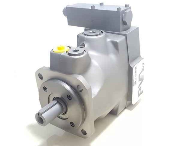
4. Open Loop Control of Axial Piston Hydraulic Pumps
Open loop control systems provide a straightforward approach to regulating axial piston pumps, making them suitable for many industrial applications.
Fundamentals of Open Loop Control
In an open loop control system, the output (flow or pressure) is controlled without feedback. The controller sends a signal to the pump based on a predefined input, without regard for the actual system response.
Key characteristics of open loop systems include:
Simplicity
Fewer components and lower complexity compared to closed loop systems.
Fast Response
No delay from feedback processing allows for rapid adjustments.
Lower Cost
Reduced sensor and control equipment requirements lower initial costs.
No Error Correction
Cannot compensate for disturbances or system variations.
Open Loop Control Methods for Axial Piston Pumps
Axial piston pumps in open loop systems are typically controlled using:
Manual Displacement Control
A mechanical lever or handwheel adjusts the swash plate angle, setting a fixed displacement. This method is simple and reliable but requires manual intervention to change settings.
Pressure-Compensated Control
The pump adjusts its displacement based on system pressure. When pressure reaches a setpoint, the pump reduces displacement to maintain constant pressure, improving energy efficiency.
Load-Sensing Control
The pump output matches the load demand by sensing the pressure differential across the system's control valves. This minimizes energy losses and heat generation.
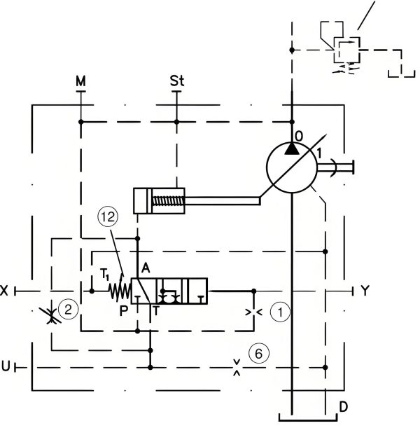
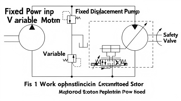
Open Loop Control System Diagram
In this typical open loop configuration, the controller sends a signal to the pump's displacement control mechanism based on an input command. The pump adjusts its output accordingly, without measuring the actual system response.hydraulic motors.
Performance Characteristics
Open loop control systems for axial piston pumps exhibit the following performance characteristics:
| Characteristic | Description |
|---|---|
| Response Time | Typically fast, as there is no feedback delay |
| Steady-State Error | May be significant due to lack of error correction |
| Disturbance Rejection | Poor; cannot compensate for external disturbances |
| Energy Efficiency | Moderate; can be optimized with pressure or load-sensing controls |
Applications of Open Loop Control
Open loop control systems are well-suited for applications where:
- Precision requirements are moderate
- Loads are relatively constant
- Cost is a primary concern
- System dynamics are well-understood and predictable
Common applications include:
5. Closed Loop Control of Piston Hydraulic Pumps
Closed loop control systems provide precise regulation of piston pumps by continuously monitoring system output and adjusting inputs accordingly.
Fundamentals of Closed Loop Control
Closed loop control systems, also known as feedback control systems, use sensors to measure the actual output of the system and compare it to a desired setpoint. The controller then adjusts the input to minimize the error between the actual and desired outputs.Hyd motor.
Key Components
- Sensor: Measures the system output (e.g., pressure, flow, position)
- Controller: Compares actual output to setpoint and calculates error
- Actuator: Adjusts the system input based on controller output
- Feedback Loop: Connects the sensor output back to the controller input
Types of Closed Loop Control
Proportional (P) Control
Output is proportional to the error signal. Simple and responsive, but may result in steady-state error.
Output = Kp × Error
Proportional-Integral (PI) Control
Includes an integral term to eliminate steady-state error. Improves accuracy but may increase overshoot.
Output = Kp × Error + Ki × ∫Error dt
Proportional-Integral-Derivative (PID) Control
Adds a derivative term to predict future error and improve stability. Widely used for its balance of performance and robustness.
Output = Kp × Error + Ki × ∫Error dt + Kd × d(Error)/dt
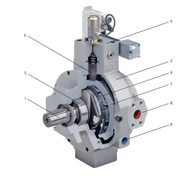
Closed Loop Control System for Piston Pumps
This diagram illustrates a typical closed loop control system for a piston pump. The system continuously measures output pressure, compares it to the desired setpoint, and adjusts the pump's displacement to maintain the desired pressure.
Advantages of Closed Loop Control
High Precision
Minimizes error between desired and actual output, ensuring accurate control.
Disturbance Rejection
Automatically compensates for external disturbances and system variations.
Dynamic Response
Quickly adjusts to changes in load or setpoint, improving system responsiveness.
Energy Efficiency
Optimizes pump output to match actual demand, reducing energy waste.
Closed Loop Control Applications
Closed loop control systems are essential for applications requiring high precision and dynamic performance, such as:
Industrial Automation
- Robotic arm control
- Precision material handling
- Automated assembly lines
Mobile Machinery
- Excavator boom control
- Wheel loader operation
- Agricultural equipment
Aerospace and Defense
- Aircraft flight control systems
- Missile guidance systems
- Naval ship stabilizers
Test and Simulation
- Hydraulic fatigue testing
- Vehicle suspension testing
- Industrial vibration simulation
6. Motor Control Principles of Piston Hydraulic Motors
Understanding the control principles of piston hydraulic motors is crucial for achieving precise motion control in various applications—particularly when carrying out tasks such as kicker motor hydraulic power lift cylinder replacement, where a clear grasp of how piston hydraulic motors regulate force and movement directly ensures the safety and accuracy of the replacement process.
Torque Control
Torque output of a hydraulic motor is directly proportional to the pressure differential across the motor and its displacement. Torque control is achieved by regulating system pressure.
T = (ΔP × D) / (2π × ηm)
Where: T = Torque, ΔP = Pressure Differential, D = Displacement, ηm = Mechanical Efficiency
Applications:
- Winches and hoists
- Conveyor drives
- Rotary actuators
Speed Control
Speed control of hydraulic motors is achieved by regulating flow rate to the motor. Common methods include:
- Throttle control using flow control valves
- Displacement control in variable motors
- Bypass control for fixed displacement motors
Applications:
- Milling machines
- Lathes and drills
- Fan and pump drives
Direction Control
Direction control of hydraulic motors is typically achieved using directional control valves, which reverse the flow of hydraulic fluid to the motor.
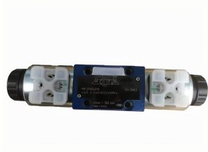
Valve Types:
- 4/3 directional control valves
- Solenoid-operated valves
- Pilot-operated valves
Variable Displacement Hydraulic Motors
Variable displacement hydraulic motors offer significant advantages in terms of efficiency and control flexibility. By adjusting the motor's displacement, it is possible to:
Constant Power Control
Variable displacement motors can maintain constant power output over a wide range of speeds by automatically adjusting displacement. This is particularly useful in applications such as:
- Machine tool spindles
- Wind turbine pitch control
- Material handling equipment
Torque-Speed Characteristics
Variable displacement motors can be controlled to provide different torque-speed characteristics, allowing optimization for specific applications:
| Mode | Characteristics | Applications |
|---|---|---|
| Constant Torque | Torque remains constant, power increases with speed | Conveyors, winches |
| Constant Power | Power remains constant, torque decreases with speed | Machine tools, pumps |
| Variable Torque | Torque varies with speed based on system requirements | Mobile machinery, robotics |
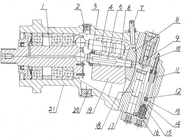
7. Radial Piston Pumps and Their Variable Control Methods
Radial piston pumps offer unique advantages in high-pressure applications—such as those within engine hydraulic systems—with specialized variable control methods to optimize performance.
Structure and Operation of Radial Piston Pumps
Radial piston pumps consist of pistons arranged radially around a central drive shaft. As the shaft rotates, an eccentric cam or ring causes the pistons to reciprocate within their cylinders, creating suction and discharge cycles.
Key Components
- Central drive shaft with eccentric cam
- Radially arranged pistons and cylinders
- Suction and discharge valves
- Oil distribution plate
- Return springs (in some designs)
Advantages of Radial Piston Pumps
Variable Control Methods
Variable control in radial piston pumps is typically achieved through:
Eccentric Adjustment
By adjusting the eccentricity of the cam or ring, the stroke length of the pistons is changed, altering the pump's displacement. This method provides continuous variable control.
Piston Deactivation
Selectively deactivating individual pistons reduces the effective displacement of the pump. This is often used in high-pressure applications where fine control is required.
Swash Plate Control
Some radial piston pumps use a swash plate mechanism similar to axial piston pumps to control displacement. This allows for precise and responsive variable control.
Radial Piston Pump Operation
As the drive shaft rotates, the eccentric cam causes the pistons to move radially in and out of their cylinders. During the suction stroke, fluid is drawn into the cylinder through the suction valve. During the discharge stroke, the fluid is forced out through the discharge valve.
Variable Displacement Mechanism
In this variable displacement design, the eccentricity of the cam can be adjusted to vary the piston stroke length. A larger eccentricity results in greater displacement, while a smaller eccentricity reduces displacement.
Applications of Radial Piston Pumps
Radial piston pumps are used in applications requiring high pressure, precision, and reliability, including:
Industrial Applications
- High-pressure hydraulic presses
- Plastic injection molding machines
- Machine tool hydraulics
- Test rigs and simulation equipment
Mobile and Offshore Applications
- Marine winches and cranes
- Offshore drilling equipment
- Mining machinery
- High-pressure cleaning systems
Specialized Applications
- Aerospace ground support equipment
- High-pressure lubrication systems
- Hydraulic torque wrenches
- Research and development equipment
8. Practical Applications of Piston Hydraulic Pumps and Motors
Piston hydraulic pumps and hydralic motors are used in a wide range of industries and applications due to their high power density, precision, and reliability.
Industrial Applications
Manufacturing Equipment
Piston pumps and motors are widely used in manufacturing for their ability to provide precise control and high power density. Applications include:
- Hydraulic presses for metal forming and stamping
- CNC machine tool drives
- Robotic arm actuators
- Conveyor systems for material handling
- Plastic injection molding machines
Power Generation
In power generation, hydraulic systems are used for critical control and actuation functions:
- Turbine control systems in hydroelectric plants
- Wind turbine pitch and yaw control
- Emergency shutdown systems in power plants
- Hydraulic couplings in transmission systems
- Test rigs for generator components
Marine and Offshore
Marine applications require robust and reliable hydraulic systems capable of operating in harsh environments:
- Ship steering systems
- Anchor winches and mooring systems
- Deck cranes and cargo handling equipment
- Offshore drilling rigs and platforms
- Subsea control systems
Mobile Applications
Construction Equipment
Construction machinery relies heavily on hydraulic systems for their power and versatility:
- Excavator boom and bucket control
- Wheel loader lifting and tilting functions
- Crane telescopic booms and winches
- Concrete pump trucks
- Road pavers and compactors
Agricultural Machinery
Modern agricultural equipment uses hydraulic systems for various functions:
- Tractor implements (loaders, mowers, plows)
- Combine harvester cutting and threshing systems
- Sprayer boom control
- Forage harvester cutter heads
- Manure spreaders and fertilizer applicators
Aerospace and Defense
Aerospace Applications
In aerospace, hydraulic systems provide critical functions requiring high reliability and power density:
- Aircraft flight control surfaces (ailerons, elevators, rudders)
- Landing gear actuation and retraction
- Braking systems
- Thrust reverser actuation
- Aircraft ground support equipment
Defense Systems
Military applications demand robust and reliable hydraulic solutions:
- Tank turret traversing and gun elevation
- Artillery recoil systems
- Missile guidance and launch systems
- Armored vehicle suspension systems
- Naval ship stabilizers and weapon systems
Specialized Applications
Medical Equipment
Hydraulic systems are used in medical equipment where precision and reliability are critical:
- Surgical tables and patient lifts
- Dental chairs and equipment
- Diagnostic imaging equipment positioning
- Medical device testing equipment
- Hospital bed adjustment mechanisms
Entertainment and Recreation
Hydraulic systems enhance performance and safety in entertainment and recreational applications:
- Amusement park ride motion systems
- Stage lifting and positioning equipment
- Marine winches for boat lifts
- Ski lift drives and controls
- High-performance vehicle suspension systems
Case Study: Hydraulic System in a Modern Excavator

Modern excavators rely on sophisticated hydraulic systems to provide the power and precision needed for heavy-duty digging and material handling. A typical excavator hydraulic system includes:
- A variable displacement piston pump to supply hydraulic fluid
- Multiple hydraulic motors for track drive and swing functions
- Hydraulic cylinders for boom, arm, and bucket movements
- Proportional control valves for precise movement control
- Load-sensing technology to optimize pump output
This integration of piston pumps, hydraulic motors, and cylinders allows the excavator to perform complex tasks with high efficiency and control.
Contact Us
Have questions about piston hydraulic pumps, hydraulic motors, or variable control systems? Our experts are ready to assist you.Optical Transceiver.
Send Us a Message
Contact Information
Address
123 Hydraulic Avenue, Fluid Dynamics City, FD 12345
Phone
+1 (555) 123-4567
info@hydraulicsolutions.com
Hours
Monday - Friday: 9:00 AM - 5:00 PM
Why Choose Us
Expertise
Over 20 years of experience in hydraulic system design and implementation.
Custom Solutions
Tailored hydraulic solutions to meet your specific application requirements.
Quality Assurance
ISO 9001 certified manufacturing processes for reliable products.
Support
Comprehensive after-sales support and technical assistance.