Fixed Hydraulic Resistance
A comprehensive technical overview of fixed hydraulic resistance components, their characteristics, and applications in hydraulic systems, including the hydraulic motor pump.
Introduction to Hydraulic Resistance
In a broad sense, any hydraulic valve port or similar structure that can locally change the flow area of a liquid flow, causing pressure loss or distributing and regulating flow under a certain pressure difference, can be called a hydraulic resistance. This includes wall orifices, short orifices, long and thin orifices, and gaps. These components play a crucial role in various hydraulic systems, including the hydraulic motor pump, where precise flow control is essential for optimal performance.
Hydraulic resistance is a fundamental concept in hydraulics, governing how fluids behave in confined spaces. Understanding hydraulic resistance is vital for designing efficient hydraulic systems, particularly in applications involving the hydraulic motor pump where energy transfer and control precision are critical factors.
The study of hydraulic resistance encompasses both theoretical analysis and practical applications, with direct implications for the design and operation of hydraulic components, including the hydraulic motor pump. Engineers must carefully consider hydraulic resistance characteristics when developing systems to ensure they meet performance requirements while maintaining energy efficiency.
Types of Hydraulic Resistance
Laminar Flow Resistance (Long and Thin Orifices)
One type of hydraulic resistance is found in long and thin orifices (l/d ≥ 4) under large Reynolds numbers, where the resistance always depends on viscosity. This type of resistance is primarily caused by viscous friction in the fluid, making it highly sensitive to changes in oil temperature.
Due to its temperature sensitivity, this form of hydraulic resistance is rarely used in hydraulic components and systems, including those incorporating the hydraulic motor pump. The performance variations caused by temperature fluctuations can lead to instability in system operation, which is undesirable in precision applications of the hydraulic motor pump.
Throttle Resistance (Orifice Plates)
The other type is throttle resistance in laminar flow that does not depend on viscosity. To reduce the impact of oil temperature changes on control accuracy and improve performance, almost all valve ports and orifices in hydraulic variable pump control technology, including those in the hydraulic motor pump, are made into thin-edged types (l/d ≤ 0.5).
This design ensures that pressure loss is primarily due to local pressure loss with almost no component of frictional resistance loss, making it independent of oil viscosity changes. This characteristic is particularly valuable in the hydraulic motor pump, where consistent performance across operating temperatures is essential.
Common Fixed Hydraulic Resistance Structures
Figure 1 illustrates common fixed hydraulic resistance structures and their flow-pressure characteristic curves, which are essential references for designing components like the hydraulic motor pump.
Figure 1: Common Fixed Hydraulic Resistance Structures and Flow-Pressure Characteristics
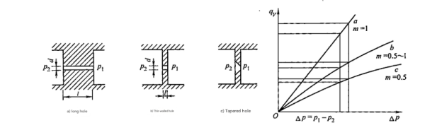
Common fixed hydraulic resistance structures
Flow-pressure characteristic curves for different hydraulic resistances
These structures form the building blocks of many hydraulic components, including the hydraulic motor pump, where they regulate fluid flow and pressure to achieve desired performance characteristics. The selection of appropriate hydraulic resistance structures directly impacts the efficiency and controllability of systems incorporating the hydraulic motor pump.
Engineers must carefully analyze these characteristic curves when designing systems with the hydraulic motor pump to ensure optimal matching between components and operating requirements. The right choice of hydraulic resistance structure can significantly enhance the performance and longevity of the hydraulic motor pump in various applications.
Detailed Analysis of Hydraulic Resistance Types
1. Long and Thin Orifices
For long and thin orifices (l/d ≥ 4) corresponding to the exponent m = 1 in flow equations, the dominant pressure loss is not local resistance loss but frictional resistance loss. This is caused by oil viscous friction and is therefore significantly affected by oil temperature changes, making it less suitable for applications in the hydraulic motor pump where consistent performance is required.
Flow in long tubes is laminar, and its flow rate qv (m³/s) can be expressed by the following formula:
qv = (πd⁴ ΔP) / (128μl)
Where:
l — length of the tube (m)
d — inner diameter of the tube (m)
μ — dynamic viscosity of the liquid (Pa·s)
ΔP — pressure difference (Pa)
This equation demonstrates the strong dependence on fluid viscosity, which limits its application in systems like the hydraulic motor pump where temperature variations are common. The performance of the hydraulic motor pump would be too variable under different operating temperatures if such resistance elements were used in critical control circuits.
Despite their limitations, long and thin orifices find applications in certain specialized systems where precise flow control under stable temperature conditions is required. However, these applications typically do not involve the hydraulic motor pump in a variable temperature environment.
2. Control Valve Ports and Thin-Edged Orifices
To reduce the impact of oil temperature changes on control accuracy and improve performance, nearly all valve ports and orifices in hydraulic variable pump control technology, including those used with the hydraulic motor pump, are made into thin-edged types (l/d ≤ 0.5). In these designs, pressure loss is primarily due to local pressure loss with almost no frictional resistance loss component.
This characteristic makes them independent of oil viscosity changes, meaning their control characteristics are not affected by oil temperature variations — a crucial advantage for the hydraulic motor pump operating in varying conditions. The flow formula for these orifices is:
qv = Cq A √(2ΔP/ρ)
Where:
Cq — flow coefficient
A — orifice flow area (m²)
ρ — liquid density (kg/m³), typically 700~900 kg/m³ for hydraulic oil
ΔP — pressure difference across the orifice (Pa)
For these different forms of thin-edged hydraulic resistance, the flow coefficient has a similar relationship curve with the Reynolds number. In the laminar flow region, the flow coefficient Cq is related to the Reynolds number Re; in the turbulent flow region, Cq is independent of Re and becomes a constant value.
This behavior is highly desirable in the hydraulic motor pump, as it ensures consistent performance across different operating conditions. The predictable characteristics of thin-edged orifices make them ideal for controlling the hydraulic motor pump in applications where precision and reliability are paramount.
Adjustment Methods for Hydraulic Resistance
Hydraulic resistance can be adjusted through various methods to control fluid flow in hydraulic systems, including those utilizing the hydraulic motor pump. The ability to adjust resistance allows for precise control of the hydraulic motor pump's output and response characteristics.
Manual Adjustment
Manual adjustment involves physical manipulation of valves or orifices to change resistance. This method is simple and cost-effective for applications where infrequent adjustments are sufficient, such as in basic hydraulic motor pump systems.
Hydraulic Adjustment
Hydraulic adjustment uses fluid pressure to modify resistance automatically. This provides responsive control suitable for dynamic systems where the hydraulic motor pump operates under varying load conditions requiring real-time adjustments.
Electric Adjustment
Electric adjustment employs solenoids or motors to vary resistance, enabling precise, computer-controlled adjustments. This is ideal for sophisticated hydraulic motor pump systems requiring automation and integration with digital control systems.
The choice of adjustment method depends on the specific requirements of the hydraulic system, including the hydraulic motor pump's operating parameters, response time needs, and automation level. Modern hydraulic systems, particularly those incorporating advanced hydraulic motor pump technology, often utilize a combination of these methods for optimal performance.
Static and Dynamic Hydraulic Resistance
Drawing on electronics' definition of nonlinear resistors, we can introduce the concepts of static hydraulic resistance R and dynamic hydraulic resistance Rd. These concepts are essential for analyzing both steady-state and transient behaviors in hydraulic systems, including those with the hydraulic motor pump.
Static Hydraulic Resistance (R)
Static hydraulic resistance is defined as the ratio of pressure difference across the hydraulic resistance to the flow rate:
R = ΔP / qv
It is a measure of the hydraulic resistance's阻碍作用 on steady-state fluid flow. This parameter is crucial when analyzing the steady-state performance of systems containing the hydraulic motor pump, as it determines pressure drops under constant flow conditions.
Dynamic Hydraulic Resistance (Rd)
Dynamic hydraulic resistance is defined as the ratio of the微小增量 of pressure difference across the hydraulic resistance to the微小增量 of flow rate:
Rd = d(ΔP) / d(qv)
It measures the hydraulic resistance's阻碍作用 on dynamic fluid flow. This parameter is particularly important when analyzing the transient response of systems with the hydraulic motor pump, such as during start-up, shutdown, or load changes.
Both static and dynamic hydraulic resistances are generally functions of pressure difference ΔP or flow rate qv. From the general flow equation, the static hydraulic resistance R can be derived as:
R = ΔP / qv = (ΔP1-m) / (K Am)
The dynamic hydraulic resistance Rd is:
Rd = d(ΔP) / d(qv) = (ΔP1-m) / (K m Am)
In these equations, if m = 1, then R = Rd = 1/(K A), meaning the hydraulic resistance is independent of flow rate. Such resistance is called linear hydraulic resistance and is characteristic of long and thin orifices. This type of resistance is less commonly used in the hydraulic motor pump due to its viscosity dependence.
If m < 1, the hydraulic resistance value is related to the pressure difference or flow rate across the resistance, making it a nonlinear hydraulic resistance. For nonlinear hydraulic resistances, the static hydraulic resistance R and dynamic hydraulic resistance Rd values are different.
A common example is the thin-edged nonlinear hydraulic resistance with an exponent m = 0.5, which follows the flow-pressure characteristic described earlier. This type of resistance is widely used in the hydraulic motor pump due to its predictable behavior and temperature insensitivity.
Thin-Edged Orifice Resistance Characteristics
For thin-edged nonlinear hydraulic resistance, which is commonly used in the hydraulic motor pump, the static and dynamic resistance values have a specific relationship that is important for system design and analysis.
Static Hydraulic Resistance for Thin-Edged Orifices
The static hydraulic resistance value R for thin-edged orifices is:
R = ΔP / qv = √(ρ/(2ΔP)) / (Cq A)
Dynamic Hydraulic Resistance for Thin-Edged Orifices
The dynamic hydraulic resistance value Rd is:
Rd = d(ΔP) / d(qv) = √(ρ/(2ΔP)) / (Cq A) × 2 = 2R
Clearly, for thin-edged nonlinear hydraulic resistance, the dynamic hydraulic resistance value Rd is twice the static hydraulic resistance R. This relationship is crucial for accurately modeling both steady-state and transient behaviors in systems incorporating the hydraulic motor pump.
Understanding this relationship allows engineers to design more effective control systems for the hydraulic motor pump, ensuring stability during both steady operation and transient conditions. The difference between static and dynamic resistance must be considered when tuning control parameters for the hydraulic motor pump.
This characteristic of thin-edged orifices makes them particularly valuable in the hydraulic motor pump, where both steady-state efficiency and dynamic response are important performance metrics. By incorporating these resistance elements, the hydraulic motor pump can achieve precise control under varying operating conditions.
Application Considerations in Hydraulic Systems
The selection between static and dynamic hydraulic resistance depends on the specific analysis being performed for the hydraulic system, including those with the hydraulic motor pump.
Steady-State Analysis
When studying the steady-state characteristics of hydraulic resistance circuits, such as calculating pressure values at various points in a pressure dividing circuit or analyzing the steady-state characteristics of a variable pump controller, static hydraulic resistance is used.
This type of analysis is essential for determining the operating points and efficiency of the hydraulic motor pump under constant load conditions. It helps engineers size components properly to ensure the hydraulic motor pump operates within its optimal range.
Dynamic Analysis
When studying the dynamic characteristics of hydraulic resistance circuits, such as analyzing the influence of variable pump controller hydraulic resistance on its dynamic characteristics, dynamic hydraulic resistance is required.
This analysis is critical for understanding how the hydraulic motor pump responds to sudden changes in load or input signals. It helps in designing control systems that ensure stable and responsive operation of the hydraulic motor pump during transient conditions.
Practical Implications for Hydraulic System Design
The proper application of hydraulic resistance principles is fundamental to designing efficient and reliable hydraulic systems, including those utilizing the hydraulic motor pump. Engineers must carefully consider both static and dynamic characteristics when selecting resistance elements for the hydraulic motor pump circuit.
For the hydraulic motor pump, the choice between different resistance types affects not only energy efficiency but also control precision and system stability. Thin-edged orifices are generally preferred for the hydraulic motor pump control due to their consistent performance across varying temperatures and operating conditions.
By leveraging the properties of both static and dynamic hydraulic resistance, engineers can optimize the hydraulic motor pump performance for specific applications, balancing factors such as response time, energy efficiency, and control accuracy to meet the system's overall requirements.
Conclusion
Hydraulic resistance is a fundamental concept in hydraulic engineering, with significant implications for the design and operation of hydraulic systems, including those incorporating the hydraulic motor pump. The distinction between static and dynamic hydraulic resistance allows for accurate analysis of both steady-state and transient behaviors.
The selection of appropriate hydraulic resistance structures, such as thin-edged orifices, is crucial for ensuring consistent performance of the hydraulic motor pump across varying operating conditions. These components provide the necessary flow control while minimizing sensitivity to temperature changes and viscosity variations.
Understanding the characteristics and applications of different hydraulic resistance types enables engineers to design more efficient, reliable, and precise hydraulic systems. This knowledge is particularly valuable in optimizing the performance of critical components like the hydraulic motor pump, which serves as a workhorse in countless industrial applications.