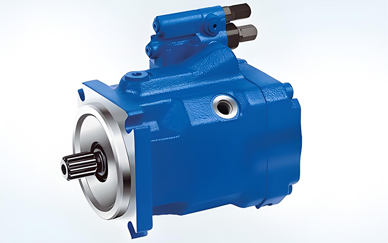
Axial piston pumps are critical components in modern hydraulic systems, providing the necessary fluid power to drive various machinery and equipment. These pumps offer exceptional efficiency, reliability, and versatility, making them suitable for a wide range of industrial applications. The ability to vary displacement – and thus flow rate – is a key feature that allows these pumps to adapt to changing system demands, optimizing energy usage and performance.
In open-loop hydraulic systems, fluid flows from the pump through the system components, including hydraulic motors and actuators, before returning to the reservoir. This configuration requires precise control mechanisms to maintain optimal performance under varying load conditions. The following sections detail the most advanced and成熟的 variable adjustment principles employed in modern axial piston open-loop hydraulic pumps.
Key Benefits of Variable Displacement
- Energy efficiency through demand-based flow control
- Precise control of hydraulic motors and actuators
- Reduced heat generation and system stress
- Enhanced system flexibility and adaptability
- Improved component lifespan and reduced maintenance
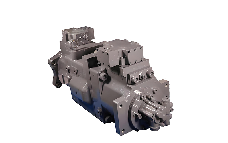
Proportional Control Displacement Adjustment Pump
The proportional control displacement adjustment pump represents one of the most sophisticated control mechanisms in modern hydraulic systems—supporting components like the hydraulic drive motor—offering precise, infinitely variable displacement control through electronic signals.
Operational Principles
At the core of the proportional control system is an electro-hydraulic proportional valve that regulates the pressure in the pump's control cylinder. This valve converts an electrical input signal (typically 0-10V or 4-20mA) into a proportional hydraulic output, which acts on a servo piston connected to the pump's swash plate.
As the electrical signal changes, the proportional valve modulates the pressure in the control chamber, causing the servo piston to move. This movement adjusts the angle of the swash plate, which directly controls the piston stroke length and thus the pump displacement. The relationship between the input signal and displacement is linear, allowing for precise control over the flow rate delivered to the system, including hydraulic motors and other actuators.
A feedback mechanism, often utilizing a position sensor on the swash plate, continuously monitors the actual displacement and sends this information back to the control system. This closed-loop feedback ensures that the pump maintains the desired displacement regardless of external factors such as pressure fluctuations or component wear.
Performance Characteristics
- Linear flow control from 0 to maximum displacement
- High dynamic response (typically 50-100 ms)
- Excellent repeatability (±1% of maximum flow)
- Low hysteresis (less than 3%)
- Compatible with various control systems and hydraulic motors
Applications
- Industrial machinery requiring precise speed control
- Material handling equipment with variable load requirements
- Mobile equipment with complex motion control needs
- Test benches for hydraulic components including hydraulic motors
- Automation systems requiring synchronized movements
Advantages in System Integration
The proportional control displacement adjustment pump offers significant advantages in system integration, particularly in modern automated systems. Its electronic control interface allows for seamless integration with PLCs, microcontrollers, and industrial control systems, enabling complex control strategies that optimize performance and energy efficiency.
When paired with appropriately sized hydraulic motors, these pumps create highly efficient drive systems that can precisely match speed and torque to load requirements. This capability is especially valuable in applications where operational conditions vary widely, as the system can continuously adjust to maintain optimal performance.
Another key advantage is the ability to implement advanced control algorithms, such as adaptive control or model predictive control, which can further enhance system performance. These algorithms can compensate for non-linearities in the system, including those introduced by hydraulic motors, temperature variations, and component aging, ensuring consistent performance throughout the system's lifespan.
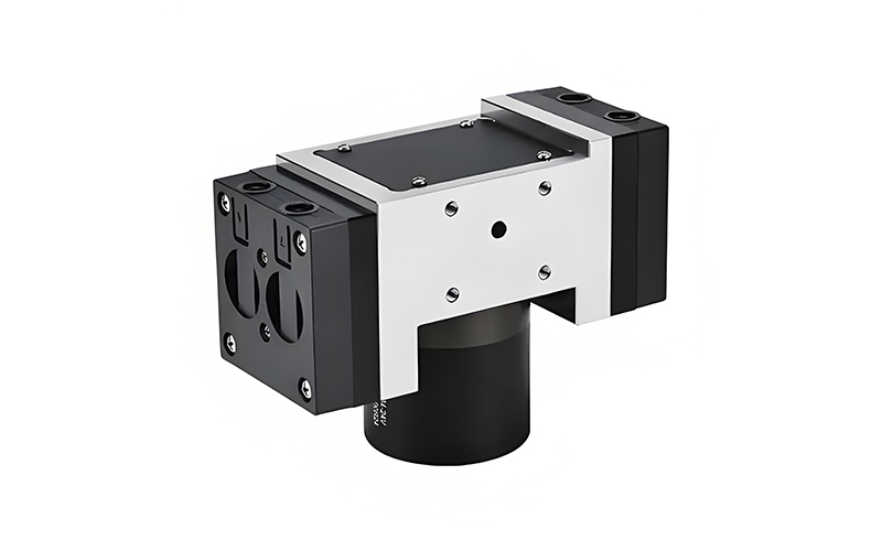
Proportional Control Pressure Adjustment Pump
The proportional control pressure adjustment pump is designed to maintain a precise system pressure regardless of flow demand, offering exceptional pressure stability and control accuracy for applications—such as hydraulic outboard motor lift and precision manufacturing equipment for optical transceiver components—where pressure regulation is critical.
Control Mechanism
This pump type incorporates a pressure compensator that continuously monitors system pressure and adjusts pump displacement to maintain the set pressure. The pressure setting is controlled proportionally via an electrical signal, allowing for remote adjustment and integration with system control architectures.
The core of the system is a proportional pressure reducing valve that sets the reference pressure for the compensator. System pressure is sensed and compared to this reference pressure. Any deviation results in a control signal that adjusts the swash plate angle, modifying pump displacement accordingly. When system pressure reaches the set point, the pump reduces displacement to nearly zero, maintaining pressure without significant flow – a state known as "standby mode."
This control strategy is particularly effective in systems where hydraulic motors or actuators operate intermittently, as the pump consumes minimal energy when not providing flow. The transition between flow delivery and standby is smooth, eliminating pressure spikes that could damage system components.
Pressure Range
Typically adjustable from 50 to 350 bar (725 to 5075 psi)
Some high-pressure models extend to 450 bar (6527 psi)
Accuracy
Set pressure maintained within ±1-2% of full scale
Excellent repeatability across operating conditions
Adjustment Features
Remote pressure setting via electronic signal
Pressure ramp control for smooth transitions
Interaction with Hydraulic Motors
In systems utilizing hydraulic motors, proportional pressure control pumps offer distinct advantages. Many hydraulic motors operate most efficiently within a specific pressure range, and maintaining this range precisely can significantly enhance overall system efficiency. The proportional pressure adjustment pump excels at this task, providing stable pressure conditions regardless of motor load variations.
For example, in a variable torque application where hydraulic motors drive different loads, the pressure control system automatically adjusts pump output to maintain the required pressure at the motor inlet. When the motor encounters increased resistance, system pressure tends to rise, prompting the pump to reduce displacement. Conversely, when load decreases, the pump increases displacement to maintain pressure, ensuring consistent motor performance.
This dynamic adjustment not only protects hydraulic motors from overpressure damage but also minimizes energy consumption. By precisely matching pressure to load requirements, the system avoids the energy losses associated with fixed-displacement pumps operating through relief valves. This makes proportional pressure control pumps ideal for applications with varying load profiles, such as material handling equipment, where hydraulic motors must adapt to different payloads.
Pressure Control vs. Load Sensing
It's important to distinguish between proportional pressure control and load-sensing systems. While both respond to system demands, they operate on different principles:
Proportional Pressure Control
- Maintains pressure at a user-specified set point
- Pressure set point adjustable via electrical signal
- Response is to system pressure, not direct load
Load-Sensing Systems
- Adjusts pressure to match actual load requirements
- Pressure determined by highest load in the system
- Directly senses load pressure at actuators or hydraulic motors
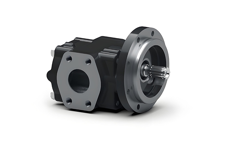
Flow Control Pump
Flow control pumps are designed to maintain a constant flow rate regardless of system pressure variations, ensuring consistent performance of the 12 volt hydraulic pump and motor and other system components under changing load conditions.
Flow Regulation Principles
The fundamental principle behind flow control pumps is maintaining a constant volume flow rate (typically measured in liters per minute or gallons per minute) regardless of system pressure. This is achieved through a feedback control system that monitors the actual flow rate and adjusts pump displacement to compensate for pressure-induced variations.
Flow sensing can be accomplished through several methods: differential pressure across a fixed orifice, turbine flow meters, or magnetic flow sensors. The sensed flow rate is compared to a reference set point, and any deviation results in an adjustment to the pump's swash plate angle. As system pressure increases, the pump automatically increases displacement to maintain the desired flow rate, and vice versa.
This capability is particularly valuable for applications where consistent speed is critical, as the flow rate directly determines the speed of hydraulic motors. By maintaining a constant flow rate to hydraulic motors, their rotational speed remains stable regardless of changes in load (and thus system pressure), ensuring consistent performance.
Types of Flow Control
Fixed Flow Control
Maintains a single preset flow rate regardless of pressure conditions. Simple design with mechanical adjustment for the flow set point. Suitable for applications with constant speed requirements for hydraulic motors.
Proportional Flow Control
Allows remote adjustment of the flow set point via an electrical signal. Enables variable speed control of hydraulic motors through flow regulation, with excellent linearity between control signal and flow rate.
Flow Priority Control
Maintains a priority flow rate to critical system components while allowing excess flow to other circuits. Ensures essential hydraulic motors receive adequate flow even during peak demand periods.
Performance Parameters
Application in Hydraulic Motor Systems
Flow control pumps play a crucial role in systems utilizing hydraulic motors, where consistent speed is often essential. Since the speed of hydraulic motors is directly proportional to the flow rate they receive (assuming constant displacement), maintaining a precise flow rate ensures stable motor speed regardless of load variations.
For example, in conveyor systems driven by hydraulic motors, a flow control pump ensures that the conveyor speed remains constant even as the load on the conveyor changes. As boxes or materials are added or removed, the pressure required to drive the hydraulic motors changes, but the flow control pump adjusts its displacement to maintain constant flow, keeping the conveyor speed consistent.
In variable speed applications, proportional flow control pumps allow operators to adjust the speed of hydraulic motors by varying the flow set point. This is particularly useful in applications such as mixers, where different materials require different agitation speeds, or in winches, where precise speed control is necessary for safe operation.
When multiple hydraulic motors operate in a system, flow control pumps can be paired with flow dividers to ensure each motor receives the appropriate flow rate. This is critical in applications such as mobile equipment with multiple functions, where different hydraulic motors may have different flow requirements but must operate simultaneously.
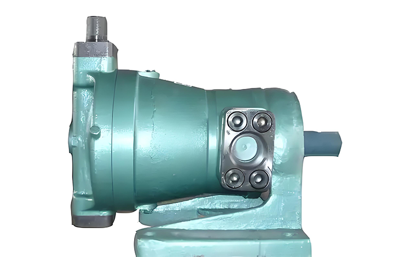
Constant Power Control Power Control
Constant power control is a sophisticated mechanism that maintains a nearly constant power output from the gas motor with hydraulic pump across a range of pressure and flow conditions, optimizing energy usage and protecting system components including hydraulic motors.
Power Regulation Fundamentals
In hydraulic systems, power (P) is the product of pressure (p) and flow rate (Q), expressed as P = p × Q. Constant power control maintains this product within a narrow range by adjusting pump displacement in response to pressure changes. When system pressure increases, the pump automatically reduces displacement (and thus flow rate), and when pressure decreases, displacement (and flow) increases.
This relationship follows a hyperbolic characteristic curve, where flow is inversely proportional to pressure. The control system continuously monitors outlet pressure and adjusts the swash plate angle to maintain operation along this predefined power curve.
The maximum power setting is typically adjustable, allowing the pump to be matched to the capabilities of the prime mover (electric motor or internal combustion engine). This prevents overloading of the drive system while ensuring optimal performance of hydraulic motors and other components.
Control Mechanism
The constant power control system utilizes a pressure-sensing piston that acts against a spring or proportional solenoid. As pressure increases, the force on the piston increases, overcoming the spring force and moving the swash plate to reduce displacement.
Modern systems often incorporate electronic control for more precise power curve shaping, allowing for multiple power settings and integration with overall system control strategies.
Power Curve Characteristics
- Cut-in pressure: point where power control begins to act
- Nominal pressure: design pressure at maximum efficiency
- Maximum pressure: pressure at minimum displacement
- Power gradient: slope of the power curve between cut-in and maximum pressure
Benefits in Systems with Hydraulic Motors
Constant power control offers significant advantages in systems utilizing hydraulic motors, particularly in applications where load conditions vary widely. By maintaining a constant power output, the pump ensures that hydraulic motors receive the appropriate combination of pressure and flow to meet changing load requirements without exceeding the capabilities of the prime mover.
For example, in mobile equipment such as excavators, hydraulic motors drive various functions including the boom, arm, and bucket. When digging into hard soil, the load on the hydraulic motors increases, causing system pressure to rise. The constant power control system reduces flow to maintain constant power, preventing engine stall while still providing the necessary torque from the hydraulic motors.
In industrial applications, constant power control protects both the prime mover and hydraulic motors from overload conditions. If a hydraulic motor becomes jammed or encounters an unexpected high load, system pressure rises rapidly. Instead of continuing to supply full flow (which could damage components), the pump reduces flow to maintain constant power, limiting torque output and preventing damage to hydraulic motors and other system components.
Another key benefit is improved energy efficiency. By matching power output to actual demand, constant power control minimizes energy waste, particularly in applications where hydraulic motors operate at varying loads. This not only reduces operating costs but also decreases heat generation, extending the life of hydraulic fluids and components.
Implementation Strategies
Mechanical-Hydraulic
Uses pressure-sensing pistons and springs to create the power curve.
Electro-Hydraulic
Combines electronic pressure sensing with proportional control valves.
Adaptive Control
Uses sensors and algorithms to optimize power delivery in real-time.
Other Constant Power Control Methods for Open-Loop Variable Pumps
Beyond the standard constant power control systems, several specialized methods have been developed to address specific application requirements, offering enhanced performance and flexibility for systems utilizing hydraulic motors, including hydraulic orbital motor.
Dual Power Control
Dual power control systems offer two distinct power settings, allowing operators to select between high-power and economy modes based on application requirements. This is particularly valuable for mobile equipment where hydraulic motors may need maximum power for heavy tasks but can operate at reduced power for lighter duties.
The transition between power modes can be manual or automatic, triggered by operating conditions or system demands. In automatic systems, sensors detect when hydraulic motors require additional power and switch modes accordingly, optimizing both performance and fuel efficiency.
Load-Sensing Power Control
Combining load sensing with power control, this method adjusts the power curve based on actual system demand rather than operating to a fixed power setting. The system continuously monitors the pressure required by hydraulic motors and other actuators, setting the pump's maximum power just above the actual load requirement.
This approach offers significant energy savings compared to fixed power control, as the pump never operates at higher power levels than necessary. It's particularly effective in multi-function systems where hydraulic motors with varying load requirements operate simultaneously.
Electronic Power Management
Advanced electronic power management systems use microprocessors to control pump output based on a variety of inputs, including prime mover speed, system pressure, temperature, and operator commands. These systems can optimize power delivery to hydraulic motors in real-time, adapting to changing conditions.
Many modern systems include communication capabilities, allowing integration with machine control networks. This enables centralized monitoring and control of multiple pumps and hydraulic motors, as well as data logging for performance analysis and maintenance planning.
Torque-Limiting Control
Torque-limiting control is a specialized form of power control that limits the torque output of the prime mover by adjusting pump displacement. This is particularly important in systems where hydraulic motors can experience sudden load spikes that could damage the engine or electric motor.
By monitoring prime mover torque (directly or indirectly through speed variations), the control system reduces pump displacement before torque reaches dangerous levels. This protects the prime mover while allowing hydraulic motors to operate within safe torque limits.
Adaptive and Intelligent Control Systems
The latest advancement in constant power control for open-loop variable pumps is the development of adaptive and intelligent control systems. These systems utilize advanced algorithms and machine learning to optimize pump performance based on operating conditions, system requirements, and historical data.
Adaptive control systems can recognize patterns in how hydraulic motors and other components operate, adjusting the power curve to match specific applications. For example, in a forestry machine, the system might learn that certain operations require hydraulic motors to operate at specific pressure and flow combinations, optimizing the power delivery for those conditions.
Intelligent systems can also predict maintenance needs by monitoring performance trends. By analyzing how the power control responds to different loads on hydraulic motors, the system can detect early signs of wear or degradation, allowing for proactive maintenance before failures occur.
These advanced control methods represent the future of hydraulic system efficiency, offering unprecedented levels of performance optimization, energy savings, and component protection. As industries continue to demand more efficient and intelligent machinery, these control systems will play an increasingly important role in maximizing the performance of both hydraulic pumps and hydraulic motors.Electronic shelf labels.
Selection Criteria for Power Control Methods
Choosing the appropriate constant power control method depends on several factors: