Fundamental Concepts of Hydraulic Motors
A Comprehensive Guide to Key Principles in Hydraulic Pump Motor Systems
The bulk modulus of hydraulic oil vs motor oil is a critical property that describes its resistance to compression. In hydraulic pump motor systems, understanding this property is essential for predicting system behavior under pressure.
Mathematically, the bulk modulus (K) is defined as the ratio of the change in pressure (ΔP) to the relative change in volume (ΔV/V):
K = -ΔP / (ΔV/V)
The bulk modulus is influenced by factors such as temperature, pressure, and the presence of dissolved gases. In hydraulic systems, a higher bulk modulus is generally preferred as it indicates less compressibility and better system response.
Hydraulic oils typically have a bulk modulus in the range of 2,000 to 3,000 MPa. However, this value can decrease significantly if the oil contains air bubbles or if the temperature rises.
Visual representation of how hydraulic oil compresses under pressure, demonstrating the concept of bulk modulus.
In hydraulic pump motor systems, the bulk modulus directly impacts system stiffness, response time, and overall efficiency.
The compressibility coefficient (β) is the reciprocal of the bulk modulus and provides a measure of how much a fluid will compress under a given pressure. In hydraulic pump motor applications, this coefficient is crucial for analyzing system dynamics.
The relationship between compressibility coefficient and bulk modulus is given by:
β = 1/K
For fluid motors, typical values of β range from approximately 3.3 x 10^-10 to 5 x 10^-10 m²/N. This small value indicates that hydraulic fluids are relatively incompressible compared to gases.
However, even this small compressibility can have significant effects in high-pressure hydraulic systems, such as those found in industrial hydraulic pump motors or mobile equipment.
The compressibility of hydraulic fluid affects:
In systems where precise control is required, such as servo-hydraulic systems, minimizing the effects of fluid compressibility is a key design consideration.
Graphical representation of fluid compressibility under varying pressure conditions.
Understanding fluid compressibility is essential for designing efficient hydraulic pump motor systems with minimal energy loss.
Fluid capacitance (C) in hydraulic systems is analogous to electrical capacitance and represents the ability of a fluid to store energy in the form of pressure. In hydraulic pump motor systems, fluid capacitance plays a vital role in system dynamics.
Fluid capacitance is calculated using the formula:
C = V / K
Where V is the volume of the fluid and K is the bulk modulus.
In hydraulic systems, fluid capacitance affects how quickly pressure changes can occur. A larger capacitance means that more fluid must be displaced to achieve a given pressure change, resulting in slower response times.
Key points about fluid capacitance:
In hydraulic pump motor applications, minimizing unnecessary fluid capacitance can improve system efficiency and response. However, in some cases, such as shock absorption, intentional capacitance may be designed into the system.
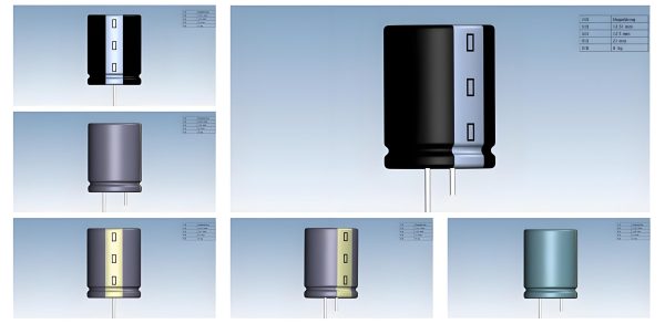
Diagram showing how fluid capacitance affects pressure changes in a hydraulic system.
Proper management of fluid capacitance is essential for optimizing the performance of hydraulic pump motor systems.
High torque hydraulic motor in hydraulic systems, dynamic closed chambers are spaces where fluid is trapped and pressure can build up or change rapidly. These chambers are critical components in hydraulic pump motor operation.
Key characteristics of dynamic closed chambers:
The pressure in a dynamic closed chamber can be calculated using the ideal gas law approximation for liquids (valid under certain conditions):
P2 = P1 + (K * ΔV) / V1
Where P1 and P2 are initial and final pressures, K is the bulk modulus, ΔV is the change in volume, and V1 is the initial volume.
In hydraulic pump motor systems, understanding pressure dynamics in closed chambers is essential for:
Special considerations must be taken for high-speed applications, where rapid changes in chamber volume can lead to cavitation or excessive pressure spikes.
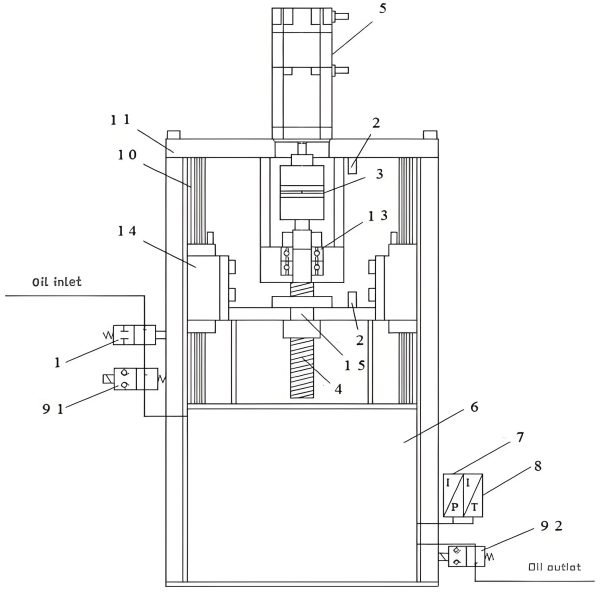
Illustration of pressure changes in a dynamic closed chamber within a hydraulic motor.
Proper design and analysis of closed chambers ensure safe and efficient operation of hydraulic pump motor systems.
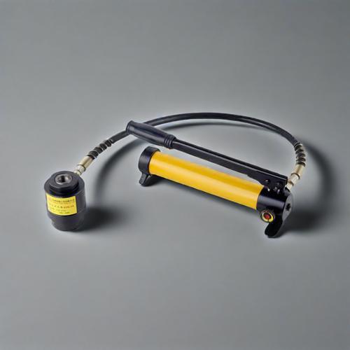
Hydraulic Drive System: Flow rate is a fundamental parameter in hydraulic systems, representing the volume of fluid passing through a given point per unit of time. In hydraulic pump motor applications, flow rate directly determines the speed of actuators and the power transmitted.
Flow rate (Q) is typically measured in liters per minute (LPM), cubic meters per second (m³/s), or gallons per minute (GPM), and is calculated using the formula:
Q = V / t
Where V is volume and t is time.
In hydraulic pump motor systems, flow rate is determined by:
Flow rate is directly related to the velocity of fluid in pipes and hoses, which can be calculated using:
v = Q / A
Where v is velocity and A is the cross-sectional area of the flow path.
Maintaining proper flow rates is critical for:
Illustration of flow rate measurement techniques in hydraulic systems.
Proper flow rate management is essential for achieving precise control in hydraulic pump motor applications.
Fixed fluid resistance, often implemented using orifices or nozzles, is a critical component in hydraulic systems. It is used to control flow, create pressure drops, and regulate system behavior in hydraulic pump motor applications.hydraulic motor pump.
Key functions of fixed fluid resistance:
The pressure drop across a fixed orifice can be calculated using the orifice equation:
ΔP = (Q² * ρ) / (2 * Cd² * A²)
Where ΔP is pressure drop, Q is flow rate, ρ is fluid density, Cd is the discharge coefficient, and A is the orifice area.
In hydraulic pump motor systems, fixed resistances are commonly used in:
Proper sizing of fixed fluid resistances is critical to ensure optimal system performance and prevent issues such as cavitation or excessive energy loss.
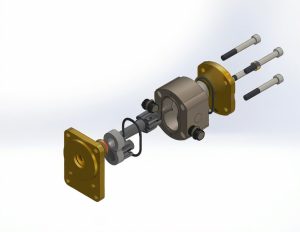
Cross-sectional view of a fixed orifice used for fluid resistance in hydraulic systems.
Precise calculation of fixed fluid resistance is essential for designing efficient hydraulic pump motor systems.
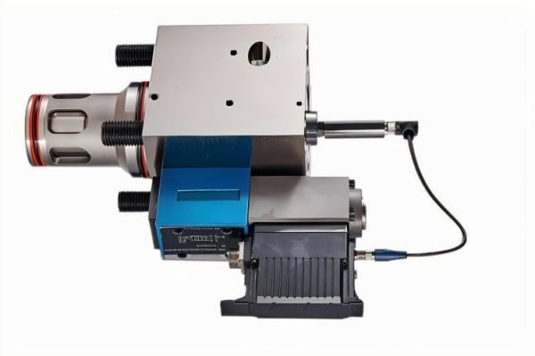
Variable fluid resistance is a key component in hydraulic control systems, particularly in pilot-operated valves and servo-hydraulic systems. In hydraulic pump motor applications, these variable resistances allow for precise control of flow and pressure.Variable displacement motor.
Pilot bridges, which use variable resistances, are essential for:
A typical pilot bridge circuit consists of:
The operation of a pilot bridge is based on the principle that the ratio of fixed to variable resistance determines the pressure distribution and, consequently, the control action.
Common types of variable resistances used in pilot bridges include:
In hydraulic pump motor systems, pilot bridges are used for functions such as speed control, torque regulation, and load sensing. Proper design and tuning of these systems are critical for achieving optimal performance and efficiency.
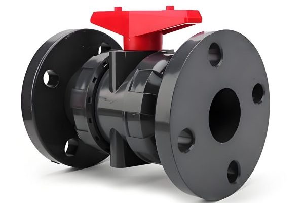
Diagram of a pilot bridge circuit using variable fluid resistance for precise control.
Variable fluid resistance in pilot bridges enables sophisticated control strategies in hydraulic pump motor systems.
Hydraulic systems can be configured as either open or closed circuits, each with distinct advantages and applications in hydraulic pump motor systems. The choice between these circuit types depends on system requirements, efficiency goals, and operational constraints.hydraulic pumps and motors.
In an open circuit, the hydraulic fluid returns to a reservoir after passing through the actuator. Key characteristics include:
In a closed circuit, the fluid flows directly from the actuator back to the pump without returning to a reservoir. Key characteristics include:
Comparison of open and closed circuits:
| Feature | Open Circuit | Closed Circuit |
|---|---|---|
| System Complexity | Lower | Higher |
| Efficiency | Moderate | Higher |
| Heat Dissipation | Better (via reservoir) | Requires additional cooling |
| Control Precision | Suitable for basic control | Ideal for precise control |
| Typical Applications | Construction equipment, industrial presses | Mobile machinery, servo systems |
In hydraulic pump motor systems, the choice between open and closed circuits depends on factors such as required efficiency, control precision, space constraints, and budget considerations.
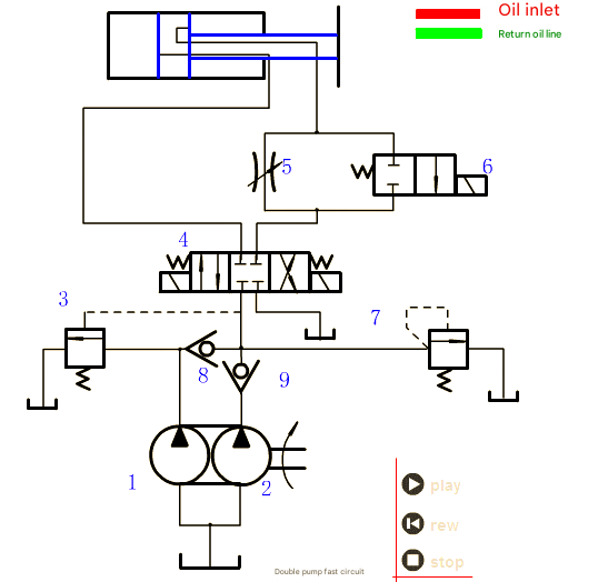
Visual comparison of open and closed hydraulic circuit configurations.
Choosing the right circuit type is critical for optimizing performance in hydraulic pump motor applications.
Flow control systems are essential for hydraulic pump and motor, serving as core components in their applications to enable precise regulation of fluid flow to actuators. These systems ensure that hydraulic machinery—driven by coordinated operation of hydraulic pump and motor—operates efficiently, safely, and with the required level of precision.
Key functions of flow control systems:
Common types of flow control valves:
Flow control systems can be classified into:
In meter-in systems, flow control is applied to the inlet of the actuator, controlling the rate at which fluid enters. This method is commonly used for extending cylinders.
In meter-out systems, flow control is applied to the outlet of the actuator, controlling the rate at which fluid exits. This method provides better control for overrunning loads and is often used in hydraulic pump motor systems.
Bleed-off systems divert excess flow back to the reservoir, maintaining a constant flow to the actuator. This method is energy-efficient for applications with variable load requirements.
Advanced flow control systems often incorporate electronic controls and sensors to provide feedback and adjust flow rates in real-time, enhancing precision and efficiency in hydraulic pump motor applications.
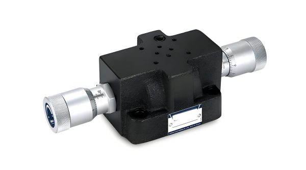
Illustration of a proportional flow control valve used in hydraulic systems.
Effective flow control systems are critical for optimizing performance in hydraulic pump motor applications.
Understanding the fundamental concepts of hydraulic motors is essential for engineers, technicians, and anyone involved in the design, operation, or maintenance of hydraulic systems. From the bulk modulus of hydraulic fluids to advanced flow control strategies, each concept plays a crucial role in the performance, efficiency, and reliability of hydraulic pump motor applications.
By mastering these principles, professionals can optimize system design, troubleshoot issues effectively, and innovate new solutions in the field of hydraulic engineering. Related lithium battery technology.
A comprehensive guide to gear, vane, and piston pumps used in hydraulic systems.
Read More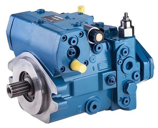
Best practices for maintaining hydraulic systems to ensure longevity and reliability.
Read More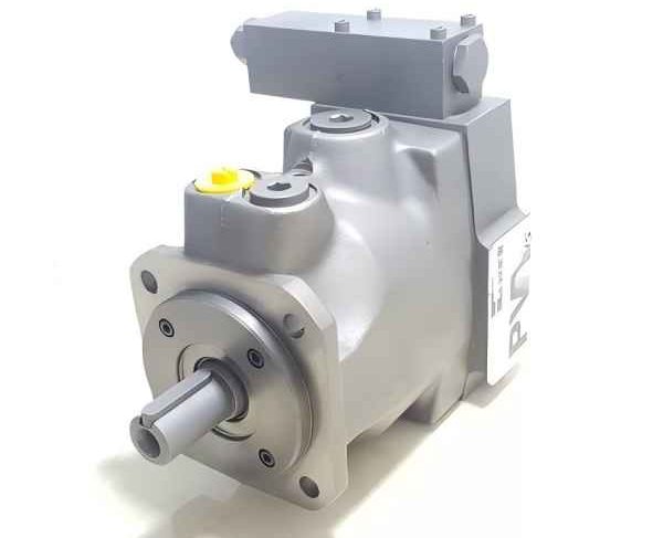
Advances in hydraulic fluid formulations and their impact on system performance.Optical Transceiver.
Read More