Understanding Open Circuit Systems
An open circuit, in hydraulic systems terminology, generally refers to a configuration where the suction line of the pump is located below the fluid level, with the tank's fluid surface open to atmospheric pressure. This design ensures that the hydraulic pump maintains better oil suction characteristics due to the balanced pressure between the inside and outside of the hydraulic tank. The hydraulic pump to motor efficiency is significantly influenced by this fundamental design aspect.
It is crucial that the inlet pipeline does not present resistance, as this would cause pressure to drop below the so-called suction pressure head or suction pressure limit. However, in certain special cases (i.e., when the suction side is under low pressure), the self-priming characteristics of piston pumps (and motors) can be utilized. This self-priming capability is a critical factor in the hydraulic pump to motor performance equation, particularly in mobile applications where pump placement relative to the reservoir may be constrained.
Considering the pump's self-priming ability and to avoid cavitation, hydraulic pumps with poor self-priming capabilities are typically limited to 75% of their rated speed, or an auxiliary pump is added for priming. Cavitation can severely damage pump components and drastically reduce the hydraulic pump to motor system lifespan, making proper priming essential for system longevity.
Key Operational Principle
In an open circuit, hydraulic oil is delivered to the actuators through the control action of directional valves and then returned to the tank in the same manner via these directional valves. This straightforward fluid path simplifies system design while maintaining efficient hydraulic pump to motor energy transfer.
Typical Characteristics
-
Suction Line Design
Short suction line length with large diameter to minimize flow resistance, optimizing hydraulic pump to motor performance by reducing pressure losses.
-
Directional Valve Sizing
Directional valves utilize flow-related pipe diameters to ensure proper flow control without excessive pressure drops in the hydraulic pump to motor circuit.
-
Filtration & Cooling
Filters and coolers are sized according to flow requirements, protecting the hydraulic pump to motor components from contamination and overheating.
-
Tank Design
Tank volume is sized as a multiple of the pump's maximum flow rate. Since oil returns to the tank after working, the tank can dissipate heat and settle contaminants, benefiting overall hydraulic pump to motor system health.
-
Pump Placement
Hydraulic pumps are positioned close to or below the tank to enhance suction conditions and maintain optimal hydraulic pump to motor efficiency.
Open Circuit Hydraulic System
A typical open circuit configuration showing the pump, reservoir, control valves, and actuators with clear fluid path from pump to motor and back to tank.
Drive speed is limited by the minimum suction pressure to prevent cavitation and maintain proper hydraulic pump to motor operation. The return stroke of the load requires control valves to maintain stable conditions, ensuring smooth operation and preventing damage to system components.
A significant advantage of open circuit systems is their ability to handle multiple loads simultaneously. Unlike closed circuits, which suffer from the disadvantage that each load must be driven by an independent pump source, open circuits excel in applications requiring multiple actuators. This flexibility makes open circuit configurations ideal for complex machinery where various functions must operate concurrently, with efficient hydraulic pump to motor energy distribution.
Building upon the basic open circuit design, hydraulic systems have evolved into various forms and types that can be classified from different perspectives. From the perspective of multi-way valve configurations, systems can be categorized as open-center and closed-center systems. This classification significantly impacts how flow is managed in the hydraulic pump to motor circuit during different operational phases.
Based on whether the hydraulic pump's flow rate changes during operation, systems can be divided into fixed-displacement and variable-displacement systems. Each configuration offers distinct advantages in terms of energy efficiency, control precision, and suitability for specific applications, directly affecting hydraulic pump to motor performance characteristics.
Open Circuit Configurations
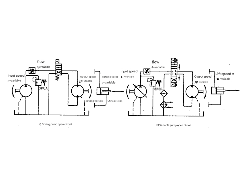
Fixed-Displacement Pump Open Circuit
Figure 1-6a shows a circuit using a fixed-displacement pump + relief valve + throttle valve to achieve speed control. This configuration exhibits both throttling and overflow losses that affect hydraulic pump to motor efficiency.
Variable-Displacement Pump Open Circuit
Figure 1-6b illustrates a speed control circuit using a variable-displacement pump with direction control via a directional valve. The relief valve functions as a safety valve, and the pump can unload when the directional valve is in the neutral position. This system eliminates major throttling losses but still has minor losses in the neutral position, optimizing hydraulic pump to motor energy transfer.
System Performance Comparison
Efficiency Characteristics
Fixed-Displacement Systems
These systems typically exhibit lower overall efficiency due to constant flow output regardless of load demand. The excess flow must be relieved through the relief valve, creating significant energy losses that reduce hydraulic pump to motor efficiency. Throttling losses in control valves further reduce efficiency, especially at partial loads.
Variable-Displacement Systems
These systems offer superior efficiency by adjusting pump output to match load requirements. By eliminating the need for constant relief valve operation and reducing throttling, variable-displacement systems optimize hydraulic pump to motor energy transfer. The ability to adjust flow output directly results in energy savings, particularly in applications with varying load demands.
Efficiency comparison between fixed and variable displacement open circuits showing hydraulic pump to motor energy transfer efficiency across different load conditions
Practical Applications
Construction Machinery
Open circuits are widely used in excavators, loaders, and bulldozers where multiple functions must operate simultaneously. The hydraulic pump to motor configuration efficiently powers boom, arm, and bucket movements while maintaining precise control.

Agricultural Equipment
Tractors, combines, and harvesters utilize open circuits to power multiple hydraulic functions from a single pump. The hydraulic pump to motor systems efficiently drive lifts, augers, and various attachments with varying flow requirements.
Industrial Machinery
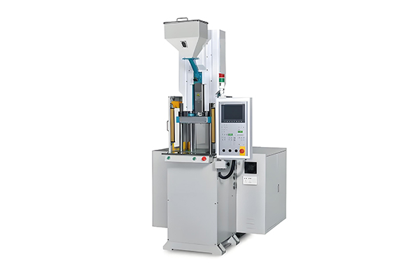
Presses, injection molding machines, and material handling equipment often employ open circuits for their flexibility. The hydraulic pump to motor configurations provide the necessary power while allowing for precise speed and force control across multiple axes.
Technical Considerations
When designing or working with open circuit hydraulic systems, several critical technical factors must be considered to ensure optimal performance and reliability. Proper system design directly impacts hydraulic pump to motor efficiency, component lifespan, and overall operational safety.
Suction Line Design
The suction line represents one of the most critical components in any open circuit system. Proper sizing and routing are essential to maintain adequate pressure at the pump inlet. A well-designed suction line minimizes pressure drops that can lead to cavitation, which severely damages pump components and reduces hydraulic pump to motor efficiency. Generally, suction lines should be as short as possible with a larger diameter than pressure lines to reduce velocity and friction losses.
Fluid Selection and Maintenance
Hydraulic fluid selection directly affects system performance, particularly in open circuits where fluid is continuously exposed to atmospheric conditions. The fluid must maintain proper viscosity across operating temperatures, resist oxidation, and provide adequate lubrication for all components in the hydraulic pump to motor circuit. Regular fluid analysis and maintenance are essential to remove contaminants and maintain optimal fluid properties, extending component life and ensuring consistent performance.
Filtration Requirements
Open circuits typically require more robust filtration than closed circuits due to the continuous exposure to potential contaminants. Proper filtration protects sensitive components in the hydraulic pump to motor system from wear and damage caused by particulate matter. Both suction line and return line filters are recommended, with the return line filter often incorporating a larger capacity to handle the full flow returning to the reservoir.
Heat Management
While open circuits benefit from the cooling effect of the reservoir, systems with high duty cycles or significant pressure drops may require additional cooling. Heat exchangers should be sized based on the total system heat load to maintain fluid temperatures within the recommended range. Excessive heat accelerates fluid degradation and reduces the efficiency of the hydraulic pump to motor components, leading to increased wear and potential system failures.
System Sizing Considerations
Proper sizing of all components is critical for efficient operation. The pump must be sized to provide adequate flow and pressure for all connected actuators, considering both simultaneous operation and pressure drops through valves and lines. Oversized components increase energy consumption and system cost, while undersized components create excessive pressure drops and reduce hydraulic pump to motor efficiency. Careful calculation of flow requirements, pressure losses, and duty cycles ensures optimal system performance.
Control Valve Selection
The selection of control valves significantly impacts system performance and efficiency. Directional control valves must be properly sized to handle the required flow rates without excessive pressure drops. In open center systems, the valve design allows fluid to return to the tank at low pressure when in the neutral position, reducing energy losses. In closed center systems, the pump can be unloaded or destroked when not providing flow, optimizing hydraulic pump to motor energy usage. The choice between these configurations depends on specific application requirements for response time, efficiency, and control precision.
Summary of Open Circuit Advantages
- Ability to power multiple loads from a single pump source, optimizing hydraulic pump to motor system complexity and cost
- Effective heat dissipation through the reservoir, reducing the need for additional cooling in many applications
- Simplified maintenance with easier access to fluid and filtration components
- Lower initial cost compared to equivalent closed circuit systems with similar functionality
- Flexibility to adapt to changing load requirements through proper valve selection
- Proven reliability in countless industrial and mobile applications, with well-understood hydraulic pump to motor performance characteristics