Table of Contents
Fluid resistance, or hydraulic resistance, is a fundamental concept in hydraulic systems, representing the opposition to fluid flow within components. This resistance is not universal—it varies drastically between hydraulic fluid vs motor oil: hydraulic fluid is formulated to minimize unnecessary resistance (ensuring efficient energy transfer in hydraulics), while motor oil’s resistance is optimized for engine lubrication, not hydraulic system performance. This resistance plays a critical role in controlling pressure, flow rate, and energy dissipation in hydraulic circuits, including those incorporating a kicker motor hydraulic power lift cylinder.
The primary functions of fluid resistance include:
- Pressure control and regulation within system components
- Flow rate limitation to protect sensitive components
- Energy conversion from hydraulic to thermal energy
- Velocity control in actuators such as the kicker motor hydraulic power lift cylinder
- Directional control by creating differential pressures
In hydraulic circuits, fluid resistance can be categorized as either fixed or variable. Fixed resistance elements include orifices, nozzles, and fixed restrictors, while variable resistance is typically provided by valves that can adjust their effective opening area. The kicker motor hydraulic power lift cylinder often utilizes both types in its control system to achieve precise positioning and force control.
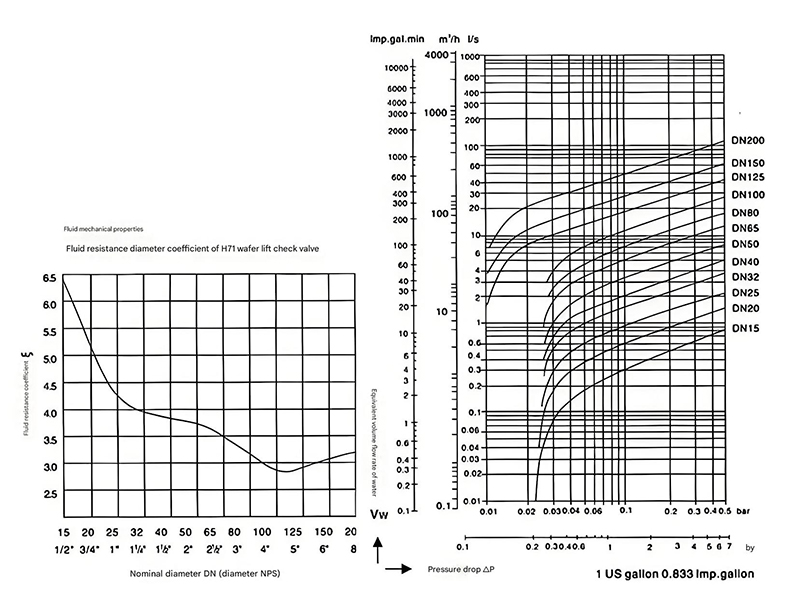
The mathematical relationship governing fluid resistance is derived from the Bernoulli equation, modified for real fluid effects. For turbulent flow through an orifice, the pressure drop (ΔP) is proportional to the square of the flow rate (Q), expressed as ΔP = KQ², where K is the resistance coefficient dependent on geometry and fluid properties. This relationship is crucial in designing hydraulic half-bridges that incorporate kicker motor hydraulic power lift cylinder technology for optimal performance.
Key Parameters Affecting Fluid Resistance
Geometric Factors
Cross-sectional area, length, and shape of flow passages, critical in kicker motor hydraulic power lift cylinder design.
Fluid Properties
Viscosity, density, and temperature, which affect performance in systems like the kicker motor hydraulic power lift cylinder.
Flow Regime
Laminar vs. turbulent flow characteristics, impacting kicker motor hydraulic power lift cylinder response.
Hydraulic half-bridges are fundamental building blocks of hydraulic control systems, consisting of two fluid resistances arranged in a specific configuration to control pressure or flow. These configurations are essential in precision control applications for diverse types of hydraulic motors—from common gear motors for low-speed, high-torque tasks to specialized variants like the kicker motor utilized in hydraulic power lift cylinders. By adjusting pressure and flow to suit the unique requirements of each hydraulic motor type, hydraulic half-bridges ensure stable and precise operation, even in scenarios like the high-demand lift control of kicker motor systems.
The primary types of hydraulic half-bridges include:
1 Fixed Resistance Half-Bridge
This configuration employs two fixed resistances (R1 and R2) in series between a supply pressure (Ps) and tank (T). The control pressure (Pc) is taken from the junction of the two resistances. While simple and cost-effective, this type offers limited adjustability, making it suitable for basic applications not requiring the precision of a kicker motor hydraulic power lift cylinder system.
The pressure ratio (Pc/Ps) is determined by the ratio of the two resistances, remaining constant unless the resistances are physically modified. This stability makes fixed resistance half-bridges ideal for applications where consistent pressure division is required without dynamic adjustment.
2 Variable Resistance Half-Bridge
In this configuration, one resistance is fixed (R1) while the other is variable (Rv). The variable resistance is typically controlled by a spool valve or similar device, allowing adjustment of the control pressure (Pc) in response to input signals. This type is commonly used in control systems for the kicker motor hydraulic power lift cylinder.
By varying Rv, the pressure ratio (Pc/Ps) can be continuously adjusted, providing proportional control over downstream components. This versatility makes variable resistance half-bridges suitable for closed-loop control systems requiring dynamic response.
3 Differential Half-Bridge
This advanced configuration features two variable resistances (Rv1 and Rv2) that are typically controlled in opposition—when one increases, the other decreases. This arrangement provides a differential output pressure that can be modulated around a neutral point, offering enhanced control sensitivity for precision applications like the kicker motor hydraulic power lift cylinder.
The differential configuration allows for both positive and negative pressure variations relative to a reference, enabling bidirectional control of hydraulic actuators with high precision and responsiveness.
4 Pressure-Compensated Half-Bridge
Designed to maintain consistent flow rates despite fluctuations in supply pressure, this type incorporates pressure compensation elements. This ensures stable performance of the kicker motor hydraulic power lift cylinder even when system pressure varies due to load changes or other disturbances.
Pressure compensation is particularly valuable in mobile hydraulic systems where supply pressure can vary significantly, ensuring precise control of actuators regardless of operating conditions.
Hydraulic Half-Bridge Configuration Comparison
| Type | Resistance Configuration | Control Precision | Typical Application |
|---|---|---|---|
| Fixed Resistance | Two fixed resistors | Low | Basic pressure division, not suitable for kicker motor hydraulic power lift cylinder control |
| Variable Resistance | One fixed, one variable | Medium | Simple actuators, basic kicker motor hydraulic power lift cylinder systems |
| Differential | Two opposing variables | High | Precision control systems, advanced kicker motor hydraulic power lift cylinder applications |
| Pressure-Compensated | Variable with compensation | Very High | Mobile hydraulics, critical kicker motor hydraulic power lift cylinder operations |
3. Hydraulic Half-Bridge Flow-Pressure Characteristics
The flow-pressure characteristics of a hydraulic half-bridge describe the relationship between pressure differentials and flow rates through the bridge configuration—characteristics that directly determine the performance of hydraulic motors and pumps (the "power core" of hydraulic systems: pumps supply pressurized fluid, motors use it to drive motion). These characteristics are therefore fundamental to understanding and designing effective hydraulic control systems, as they ensure hydraulic motors and pumps operate within optimal pressure-flow ranges (e.g., preventing motor stalling from insufficient flow or pump damage from excessive pressure). This includes systems utilizing a kicker motor hydraulic power lift cylinder, where the kicker motor’s lift force and speed depend entirely on the half-bridge’s flow-pressure output.
For any hydraulic resistance, the flow rate (Q) through the resistance is a function of the pressure drop (ΔP) across it. This relationship is typically expressed as:
Q = K · √(ΔP)
Where K is a constant dependent on fluid properties and geometry
This equation assumes turbulent flow, which is common in most hydraulic systems operating within typical industrial ranges. For laminar flow, the relationship becomes linear (Q ∝ ΔP), but this is less common in high-performance systems like those incorporating a kicker motor hydraulic power lift cylinder.
In a hydraulic half-bridge, the interaction between two resistances creates a pressure division that determines the control pressure (Pc) relative to the supply pressure (Ps). The flow through each resistance must be equal in a static condition, leading to specific relationships between the resistances and pressures.
For a half-bridge with resistances R1 and R2, the pressure ratio is given by Pc/Ps = R2/(R1+R2) under certain conditions. This relationship forms the basis for designing half-bridges that provide the desired control characteristics for systems like the kicker motor hydraulic power lift cylinder.
Flow-Pressure Relationship
Dynamic Characteristics
In dynamic conditions, the flow-pressure characteristics become more complex due to transient effects, fluid compressibility, and inertia. These factors are particularly important in high-speed applications involving a kicker motor hydraulic power lift cylinder where rapid response is required.
The dynamic response of a hydraulic half-bridge is influenced by:
- Volume of fluid in the control chamber
- Bulk modulus of the hydraulic fluid
- Mass of moving components in the kicker motor hydraulic power lift cylinder
- Frictional forces within the system
- Response time of the variable resistance element
These factors combine to create a system with specific natural frequency and damping characteristics that must be matched to the application requirements for stable operation.
Nonlinear Effects
While the basic flow equation suggests a square-root relationship between flow and pressure, real-world systems exhibit additional nonlinearities that must be considered, especially in precision applications like the kicker motor hydraulic power lift cylinder.
Significant nonlinear effects include:
- Flow force variations with spool position in valve-controlled systems
- Fluid viscosity changes with temperature affecting resistance
- Cavitation at low pressure regions, disrupting flow patterns
- Leakage flows that become significant at low pressure differentials
- Boundary layer effects in small orifices
Modern control algorithms often include compensation for these nonlinearities to achieve the high precision required in applications utilizing a kicker motor hydraulic power lift cylinder.
4. Hydraulic Half-Bridge Construction Principles
Pressure Rating Matching
All components of the half-bridge must be rated for the maximum system pressure, including pressure spikes that may occur during operation of the kicker motor hydraulic power lift cylinder. This prevents component failure and ensures safety.
Flow Capacity Sizing
Resistance elements must be sized to handle the required flow rates without excessive pressure drop, ensuring efficient operation of the kicker motor hydraulic power lift cylinder while maintaining control precision.
Compatibility with Fluid
Materials used in construction must be compatible with the hydraulic fluid to prevent corrosion, swelling, or degradation that could affect performance of the kicker motor hydraulic power lift cylinder system.
Another critical principle is the minimization of internal volume in the control lines and chambers. This reduces fluid compressibility effects and improves the dynamic response of the system, which is particularly important for fast-acting systems like the kicker motor hydraulic power lift cylinder. Smaller volumes allow for quicker pressure changes and more responsive control.
Symmetry in design is especially important for differential half-bridges. Symmetrical flow paths ensure balanced performance in both directions of operation, preventing bias in the control of the kicker motor hydraulic power lift cylinder. This symmetry should extend to manufacturing tolerances to maintain performance consistency.
Leakage control is another vital principle in half-bridge construction. Minimizing internal and external leakage ensures efficient operation and maintains the pressure relationships necessary for accurate control. This is achieved through precise machining, appropriate clearances, and effective sealing techniques compatible with the operating conditions of the kicker motor hydraulic power lift cylinder.
Finally, thermal management considerations are essential in half-bridge design. The energy dissipation in fluid resistances generates heat that can affect fluid properties and component performance. Adequate cooling or heat dissipation provisions must be made, especially in high-power applications involving the kicker motor hydraulic power lift cylinder operating under heavy loads for extended periods.
Manufacturing Considerations for Hydraulic Half-Bridges
Precision manufacturing is critical to achieving the designed performance characteristics of hydraulic half-bridges. Tolerances in the order of micrometers are often required for critical dimensions, especially for the variable resistance elements that control the kicker motor hydraulic power lift cylinder.
Surface Finish
Smooth surface finishes reduce friction, minimize flow disturbances, and prevent fluid degradation in components controlling the kicker motor hydraulic power lift cylinder.
Dimensional Accuracy
Precise dimensions ensure consistent resistance characteristics and proper valve operation in kicker motor hydraulic power lift cylinder control systems.
Material Selection
Appropriate materials provide the necessary strength, wear resistance, and corrosion resistance for kicker motor hydraulic power lift cylinder applications.
Quality Control
Rigorous testing ensures each component meets specifications for reliable operation in kicker motor hydraulic power lift cylinder systems.
5. Requirements for Pilot-Controlled Hydraulic Bridges
Pilot-controlled hydraulic bridges, which use a smaller control (pilot) system to operate a larger main system, have specific requirements for hydraulic motor manufacturers to ensure reliable and precise operation, particularly when controlling high-power actuators like the kicker motor hydraulic power lift cylinder.
Primary requirements include:
Adequate Amplification Ratio
The pilot system must provide sufficient hydraulic amplification to operate the main valve against the forces generated by the main system pressure. This ratio is critical when controlling high-force actuators like the kicker motor hydraulic power lift cylinder.
Stability Under All Operating Conditions
The pilot control system must maintain stability across the entire range of operating pressures and flow rates encountered in kicker motor hydraulic power lift cylinder applications, preventing oscillations or instability.
Environmental Robustness
Pilot systems must resist contamination, temperature extremes, and vibration—factors commonly encountered in industrial environments where kicker motor hydraulic power lift cylinder systems operate.
Low Power Consumption
The pilot system should consume minimal power while maintaining performance, especially in mobile applications where energy efficiency is critical for kicker motor hydraulic power lift cylinder operation.
Additionally, pilot-controlled bridges require precise matching between the pilot and main stages. The pilot stage must have sufficient authority to overcome any friction or hysteresis in the main stage while maintaining linearity across the operating range of the kicker motor hydraulic power lift cylinder.
Dynamic response requirements are also critical. The pilot system must respond quickly enough to meet the overall system response requirements without introducing instability. This is particularly important in high-performance applications where the kicker motor hydraulic power lift cylinder must react rapidly to changing conditions.
Performance Parameters for Pilot-Controlled Systems
Response Time
Must be sufficient for kicker motor hydraulic power lift cylinder dynamics
Control Range
Adequate to cover full kicker motor hydraulic power lift cylinder operation
Linearity
Ensures predictable kicker motor hydraulic power lift cylinder behavior
Fail-Safe Operation
Protects kicker motor hydraulic power lift cylinder in fault conditions
Spool-type hydraulic amplifiers are essential components in hydraulic control systems, converting small mechanical or hydraulic input signals into larger hydraulic output power. These devices, used to control hydraulic pony motor and other high-power actuators like the kicker motor hydraulic power lift cylinder, operate with precision and responsiveness.
The basic design consists of a cylindrical spool that slides within a sleeve, controlling the flow of hydraulic fluid through precisely machined ports. As the spool moves, it opens or closes flow paths, varying the resistance to fluid flow and thus controlling pressure or flow rate to the connected actuator—this includes not just the kicker motor hydraulic power lift cylinder, but also hydraulic motors, which rely on both regulated fluid flow and a secure hydraulic motor mount to function reliably. The hydraulic motor mount acts as a critical interface between the motor and the machinery frame: it absorbs operational shocks, prevents axial/radial movement during high-torque output, and ensures the motor’s fluid inlets/outlets stay aligned with the hydraulic lines. This alignment is essential for maintaining consistent fluid flow (as controlled by the spool valve), making the hydraulic motor mount an integral part of the actuator’s overall performance system.
Key Design Features
- Precision-machined spool and sleeve with minimal clearance to control leakage while allowing smooth movement
- Strategically positioned ports that control flow to and from the kicker motor hydraulic power lift cylinder
- Land configurations designed for specific flow characteristics (linear, equal percentage, etc.)
- Actuation mechanisms (solenoid, hydraulic pilot, manual) matched to input signal type
- Feedback mechanisms for position sensing in servo applications involving kicker motor hydraulic power lift cylinder control
Performance Characteristics
- Flow gain: The relationship between spool displacement and output flow to the kicker motor hydraulic power lift cylinder
- Pressure gain: The ratio of output pressure change to input signal change
- Null bias: The spool position that results in zero flow to the kicker motor hydraulic power lift cylinder
- Dynamic response: The speed at which the amplifier can change its output in response to input signals
- Pressure override: The change in flow rate to the kicker motor hydraulic power lift cylinder with varying load pressure
Spool-type amplifiers are classified based on their number of ports and flow paths. The most common configurations include 2-way, 3-way, and 4-way valves. For controlling a kicker motor hydraulic power lift cylinder, 4-way valves are typically used as they can control both extension and retraction by directing flow to either side of the piston while allowing return flow from the opposite side.
Modern spool-type amplifiers often incorporate position feedback and electronic control to achieve high-performance servo operation. This allows for precise control of the kicker motor hydraulic power lift cylinder position, velocity, or force with excellent dynamic response and accuracy.
Types of Spool Valves for Hydraulic Amplification
| Valve Type | Configuration | Applications | Advantages |
|---|---|---|---|
| 2-Way Valve | Controls flow in one direction | Flow control for kicker motor hydraulic power lift cylinder auxiliary functions | Simple, low cost, reliable |
| 3-Way Valve | Connects inlet to outlet or outlet to tank | Single-acting kicker motor hydraulic power lift cylinder control | Compact, efficient for single-direction control |
| 4-Way Valve | Controls flow to both sides of actuator | Double-acting kicker motor hydraulic power lift cylinder control | Complete control of actuator motion |
| Servo Valve | 4-way with position feedback | Precision kicker motor hydraulic power lift cylinder control systems | High accuracy, excellent dynamic response |
Feedback mechanisms are essential components in closed-loop hydraulic control systems, providing information about the actual system state to compare with the desired state. These mechanisms are critical for achieving precise control of actuators like the kicker motor hydraulic power lift cylinder and integrated systems such as the hydraulic motor gearbox—a key assembly that combines hydraulic motor torque with gear reduction to deliver controlled rotational power in heavy machinery. For hydraulic motor gearboxes, feedback ensures the gear ratio adjustments and motor speed align with load demands, preventing overloading and ensuring smooth operation. By enabling error correction and improving system stability, feedback mechanisms enhance performance across all such hydraulic actuators and transmissions.
In hydraulic systems, feedback mechanisms typically measure parameters such as position, velocity, pressure, or force, depending on the control requirements of the kicker motor hydraulic power lift cylinder. This measured information is compared to the command signal, and the difference (error) is used to adjust the system output.
Common Types of Feedback Mechanisms
Mechanical Feedback
Uses physical linkages to transmit position information from the kicker motor hydraulic power lift cylinder or valve to the control element. This simple, reliable method is common in proportional valves and basic servo systems.
Advantages include simplicity, no electrical components, and intrinsic safety in hazardous environments. Limitations include mechanical wear and limited bandwidth compared to other methods.
Hydraulic Feedback
Utilizes pressure signals or fluid flow to provide feedback about the kicker motor hydraulic power lift cylinder operation. This can be achieved through pressure taps, flow sensors, or specialized pilot lines that create pressure differentials proportional to system parameters.
Advantages include compatibility with hydraulic environments and intrinsic damping. Limitations include potential contamination issues and lower precision compared to electronic methods.
Electronic Feedback
Incorporates transducers to convert physical parameters of the kicker motor hydraulic power lift cylinder (position, velocity, pressure) into electrical signals. Common sensors include potentiometers, LVDTs (Linear Variable Differential Transformers), pressure transducers, and encoders.
Advantages include high precision, flexibility in signal processing, and compatibility with digital control systems. Limitations may include sensitivity to electrical noise and the need for power supplies.
The choice of feedback mechanism depends on several factors including required accuracy, environmental conditions, response speed, and cost constraints for the kicker motor hydraulic power lift cylinder application. High-performance systems often combine multiple feedback types to leverage the advantages of each.
Feedback System Performance Metrics
- Sensitivity: Ability to detect small changes in kicker motor hydraulic power lift cylinder position
- Bandwidth: Frequency range over which accurate feedback is provided
- Linearity: Degree to which output is proportional to kicker motor hydraulic power lift cylinder motion
- Hysteresis: Error between increasing and decreasing measurements
- Environmental robustness: Performance stability under varying conditions
Integration of Feedback with Hydraulic Half-Bridges
The effective integration of feedback mechanisms with hydraulic half-bridges creates a closed-loop control system that can precisely regulate the performance of the kicker motor hydraulic power lift cylinder. This integration involves several key considerations:
Signal Conditioning
Feedback signals from kicker motor hydraulic power lift cylinder sensors often require amplification, filtering, or conversion to be compatible with the control system.
Error Calculation
The difference between desired and actual kicker motor hydraulic power lift cylinder performance must be computed accurately for effective correction.
Control Algorithm
Proportional-Integral-Derivative (PID) or other algorithms convert error signals into appropriate half-bridge control signals for the kicker motor hydraulic power lift cylinder.
When properly designed, this integration results in a system that can maintain precise control of the kicker motor hydraulic power lift cylinder despite variations in load, temperature, and other environmental factors, while providing excellent dynamic response and stability.
Key Takeaways
Understanding hydraulic half-bridges and servo valve technology is essential for designing and maintaining precise control systems, including those utilizing kicker motor hydraulic power lift cylinder technology.
Fluid Resistance
Controls pressure and flow in hydraulic systems, essential for kicker motor hydraulic power lift cylinder operation.Electronic shelf labels.
Half-Bridge Types
Fixed, variable, differential, and compensated configurations offer different control capabilities for kicker motor hydraulic power lift cylinder systems.Optical Transceiver.
Flow Characteristics
The Q-ΔP relationship determines how kicker motor hydraulic power lift cylinder systems respond to control inputs.
Feedback Systems
Critical for closed-loop precision control of kicker motor hydraulic power lift cylinder operation.