Variable Hydraulic Resistances in Motor Pilot Fluid Bridges
A comprehensive analysis of sliding valves, poppet valves, and nozzle flapper valves in hydraulic control systems, including their application with variable displacement motor technology.
Introduction to Hydraulic Resistance in Pilot Circuits
In hydraulic systems, particularly those involving precision control mechanisms like the variable displacement motor, the role of pilot fluid bridges is crucial for achieving accurate and responsive operation. These specialized fluid bridges rely heavily on variable hydraulic resistances to modulate flow rates and pressures within the system. The variable displacement motor, known for its ability to adjust output speed and torque by altering displacement volume, depends on these precise control mechanisms to function optimally across varying load conditions.
The fundamental principle behind pilot fluid bridges involves the strategic arrangement of hydraulic components to control the main flow in a system. By manipulating smaller control flows, these bridges enable efficient regulation of larger hydraulic circuits, reducing the energy required for control operations. This is especially beneficial in systems utilizing a variable displacement motor, where energy efficiency and precise control are paramount concerns.
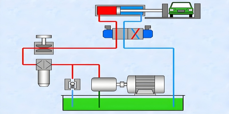
Fig. 1: Schematic representation of a hydraulic control system with pilot fluid bridge and variable displacement motor integration
This technical overview focuses on the three primary types of variable hydraulic resistances employed in pilot fluid bridges: sliding valves, poppet valves, and nozzle flapper valves. Each type offers unique characteristics that make them suitable for specific applications, particularly when paired with a variable displacement motor in complex hydraulic systems. Understanding their design principles, performance characteristics, and operational advantages is essential for engineers and technicians working with modern hydraulic control systems.
Primary Types of Variable Hydraulic Resistances
Sliding Valves
Sliding valves represent one of the most common variable hydraulic resistances used in pilot fluid bridges, often integrated with variable displacement motor systems for enhanced control precision.
Learn more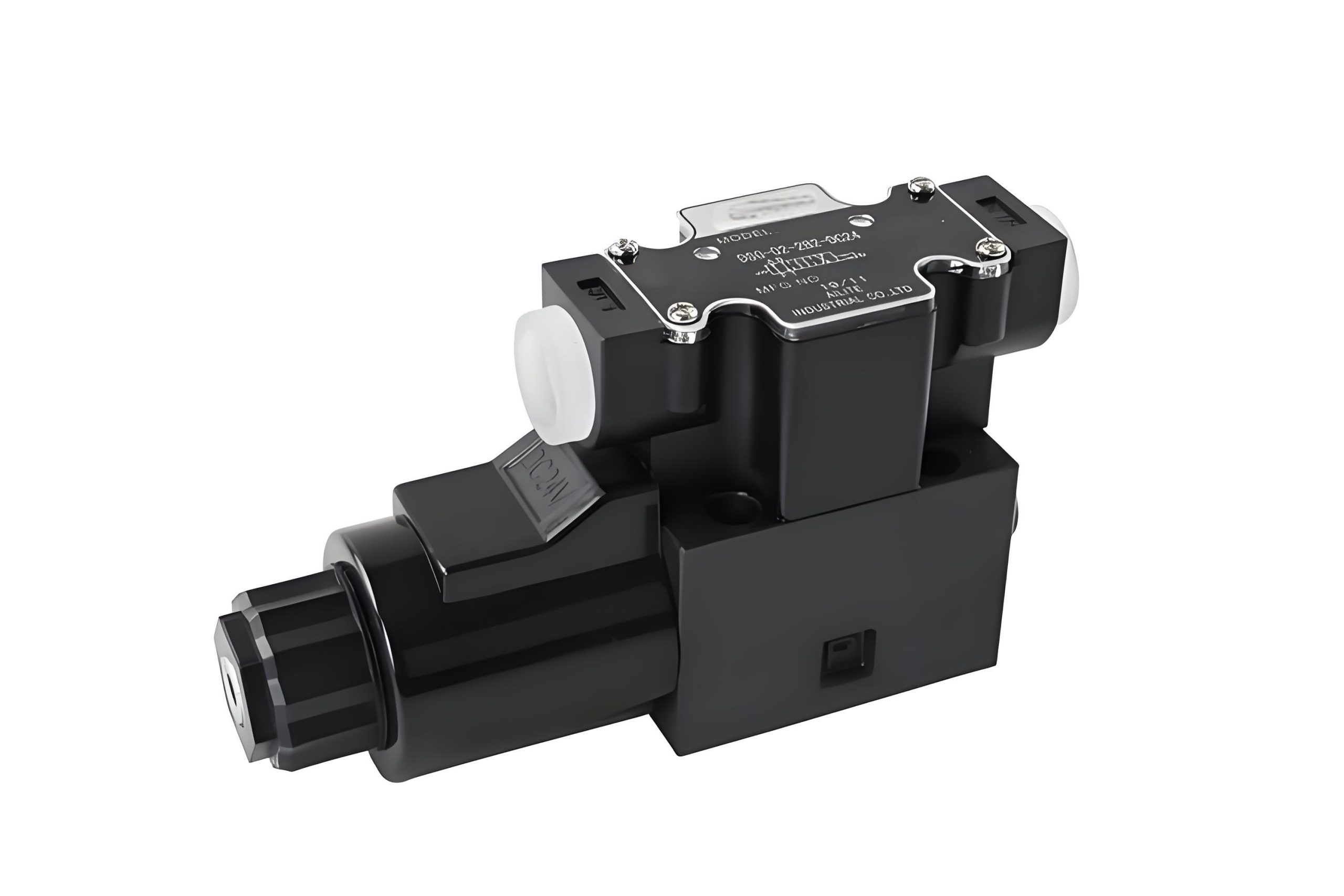
Poppet Valves
Poppet valves offer distinct advantages in pressure control applications, making them ideal for variable displacement motor systems requiring precise pressure regulation.
Learn more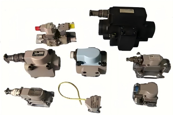
Nozzle Flapper Valves
These precision valves provide exceptional sensitivity, making them perfect for variable displacement motor control systems where minute adjustments are critical.
Learn moreSliding Valves
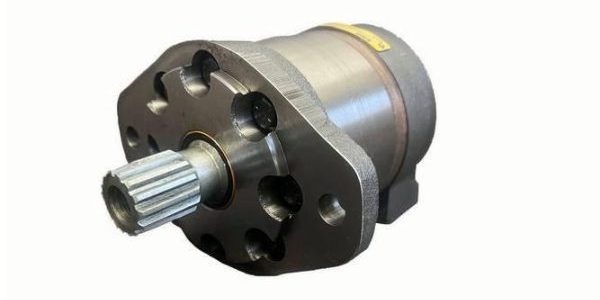
Sliding valves, also known as spool valves, constitute a fundamental category of variable hydraulic resistances in pilot fluid bridges, frequently employed in conjunction with variable displacement motor systems. Their design consists of a cylindrical spool that slides within a matching bore, with strategically positioned grooves and lands that control the flow path between ports as the spool moves.
In variable displacement motor applications, sliding valves offer exceptional control characteristics due to their linear flow response to spool displacement. This linearity simplifies control algorithms and enhances system predictability, which is crucial for maintaining optimal performance of a variable displacement motor across its operating range. The ability to precisely meter flow makes sliding valves particularly valuable in systems where the variable displacement motor must maintain specific speed or torque profiles.
The construction of sliding valves allows for multiple flow paths and configurations, from simple two-way valves to complex multi-port designs. This versatility makes them adaptable to various hydraulic circuit requirements, including those of advanced variable displacement motor systems. The spool's movement can be controlled by mechanical, hydraulic, or electrical means, with proportional solenoid actuation being common in modern variable displacement motor control systems for its precision and responsiveness.
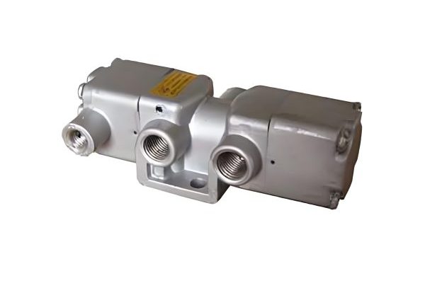
Fig. 2: Cross-sectional view of a sliding valve showing spool position and flow control mechanism
Design Characteristics
- Precision-machined spool and bore with minimal clearance to prevent leakage while allowing smooth movement
- Sharp-edged orifices (l/d ≤ 0.5) to ensure consistent flow characteristics independent of fluid viscosity
- Balanced or unbalanced spool designs, with balanced versions reducing actuation forces in variable displacement motor systems
- Various spool land configurations to achieve specific flow characteristics for variable displacement motor control
- Materials selected for wear resistance and compatibility with hydraulic fluids used in variable displacement motor systems
Performance Advantages in Variable Displacement Motor Systems
Linear Flow Characteristics
Flow rate changes proportionally with spool displacement, simplifying control algorithms for variable displacement motor systems.
Low Hysteresis
Minimal difference between opening and closing characteristics ensures precise control of variable displacement motor operation.
High Flow Capacity
Able to handle the flow rates required for effective control of larger variable displacement motor systems.
Versatile Configuration
Adaptable to various circuit requirements, making them suitable for diverse variable displacement motor applications.
When integrated into variable displacement motor control systems, sliding valves contribute significantly to overall system efficiency and performance. Their ability to modulate flow with high precision allows the variable displacement motor to maintain optimal operating parameters even under varying load conditions. Additionally, the robust construction of sliding valves ensures long service life in the demanding environments where variable displacement motor systems typically operate.
Poppet Valves
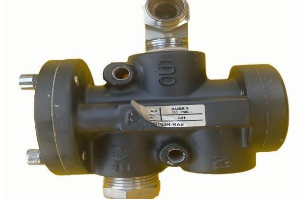
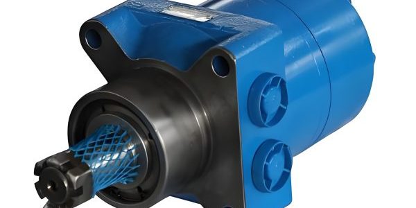
Fig. 3: Poppet valve design showing the锥形密封面和阀座配合 (conical sealing surface and seat interface)
Poppet valves, characterized by their conical or spherical closing element (poppet) that seats against a matching valve seat, represent another critical type of variable hydraulic resistance in pilot fluid bridges, often utilized in variable displacement motor control systems. Their design offers unique advantages in applications requiring reliable sealing and pressure control, making them particularly valuable for variable displacement motor systems operating under high-pressure conditions.
In variable displacement motor applications, poppet valves excel at providing precise pressure regulation and flow control with minimal leakage. The poppet's seating action creates a tight seal when closed, preventing unwanted flow that could compromise the efficiency of a variable displacement motor. When open, the poppet's geometry creates a sharp-edged orifice that maintains consistent flow characteristics regardless of fluid viscosity changes, ensuring stable performance of the variable displacement motor across operating temperatures.
The operation of a poppet valve involves moving the poppet away from its seat to create an annular flow area. This flow area can be varied by adjusting the lift distance between the poppet and seat, allowing for precise control of flow rate—a critical factor in regulating the performance of a variable displacement motor. The force required to actuate the poppet can be derived from various sources, including springs, hydraulic pressure, or electrical actuators, with proportional control options available for integration into advanced variable displacement motor control systems.
Design Features
| Feature | Description | Benefit in Variable Displacement Motor Systems |
|---|---|---|
| Conical Sealing Surface | Precision-ground cone that mates with valve seat | Ensures tight seal, minimizing leakage in variable displacement motor circuits |
| Sharp-Edged Orifice | Thin, sharp edges on flow passages (l/d ≤ 0.5) | Flow characteristics independent of viscosity, stable variable displacement motor performance |
| Spring Mechanism | Biases poppet toward closed position | Provides fail-safe operation for variable displacement motor systems |
| Actuation Interface | Connection point for control force application | Enables integration with variable displacement motor control systems |
Applications with Variable Displacement Motors
Poppet valves find extensive use in variable displacement motor systems where their unique characteristics provide distinct advantages. One key application is in the pressure compensators that maintain optimal operating pressure for variable displacement motors under changing load conditions. The poppet valve's ability to precisely control pressure ensures that the variable displacement motor receives consistent supply pressure, preventing performance degradation and improving energy efficiency.
Another important application is in the servo control loops that regulate variable displacement motor output. By modulating the control pressure supplied to the variable displacement motor's displacement control mechanism, poppet valves enable precise adjustment of motor output. This allows the variable displacement motor to maintain exact speed or torque requirements even as load conditions change, enhancing overall system performance.
In high-pressure variable displacement motor systems, poppet valves' superior sealing capabilities become particularly valuable. Their ability to maintain a tight seal under high pressures reduces internal leakage, which would otherwise waste energy and reduce the efficiency of the variable displacement motor. This makes poppet valves an excellent choice for heavy-duty applications where the variable displacement motor must operate under demanding conditions for extended periods.
Nozzle Flapper Valves
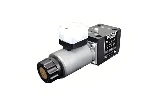
Nozzle flapper valves represent a highly sensitive type of variable hydraulic resistance, widely used in precision pilot fluid bridges, particularly in conjunction with high-performance variable displacement motor systems. Their design consists of a fixed nozzle and a movable flapper (or baffle) whose position relative to the nozzle outlet controls the flow rate and pressure drop across the valve. This configuration offers exceptional sensitivity to small flapper movements, making them ideal for applications where precise control of a variable displacement motor is required.
In variable displacement motor control systems, nozzle flapper valves provide the high sensitivity needed for accurate regulation of motor displacement. Even minute movements of the flapper result in measurable changes in flow and pressure, allowing for precise adjustment of the variable displacement motor's output characteristics. This level of control is particularly valuable in applications where the variable displacement motor must maintain exact speed or torque parameters, such as in precision manufacturing equipment or advanced mobile machinery.
The operation of a nozzle flapper valve involves fluid flowing through the nozzle toward the flapper. As the flapper moves closer to the nozzle, the restriction increases, causing pressure to rise in the supply line to the nozzle. This pressure change can be used directly to control actuators or can be amplified by additional hydraulic components to control larger variable displacement motor systems. The relationship between flapper position and pressure output is highly linear, simplifying the control algorithms used to regulate variable displacement motor performance.
Fig. 4: Nozzle flapper valve configuration demonstrating how flapper position controls flow characteristics
Operational Principles
Fig. 5: Relationship between flapper displacement and output pressure in a nozzle flapper valve system for variable displacement motor control
Advantages in Variable Displacement Motor Control
High Sensitivity
Responds to minute control movements, enabling precise regulation of variable displacement motor performance parameters.
Linear Response
Exhibits highly linear characteristics between input and output, simplifying variable displacement motor control algorithms.
Fast Response
Rapid dynamic response enables quick adjustments to variable displacement motor output during transient conditions.
When integrated into variable displacement motor control systems, nozzle flapper valves typically serve as the first stage in a two-stage control architecture. Their high sensitivity allows them to respond to small electrical or mechanical input signals, while their output pressure controls a larger second-stage valve that directly regulates the variable displacement motor's displacement mechanism. This configuration combines the precision of the nozzle flapper valve with the flow capacity needed to operate the variable displacement motor's control elements effectively.
The performance of nozzle flapper valves in variable displacement motor systems can be further enhanced through the use of feedback mechanisms. By incorporating position feedback from the variable displacement motor's swash plate or other displacement-control elements, the system can continuously adjust the nozzle flapper valve's output to maintain the desired motor performance. This closed-loop control approach significantly improves the accuracy and stability of the variable displacement motor, particularly under varying load and temperature conditions.
Common Advantages of Variable Hydraulic Resistances
While sliding valves, poppet valves, and nozzle flapper valves each possess unique characteristics that make them suitable for specific applications, they share several common advantages that make them ideal for use in pilot fluid bridges, particularly in conjunction with variable displacement motor systems. These shared attributes contribute to their widespread adoption in hydraulic control systems where precision, reliability, and efficiency are paramount concerns for variable displacement motor operation.
Simplified Construction for Variable Displacement Motor Integration
All three types of variable hydraulic resistances feature designs that facilitate the creation of variable small flow cross-sections, which is essential for precise control of fluid flow in pilot circuits. This characteristic allows for straightforward integration with variable displacement motor control systems, as the compact size and simplified construction of these valves make them easy to incorporate into the overall hydraulic architecture of variable displacement motor systems.
The relative simplicity of these valve designs also contributes to lower manufacturing costs and improved reliability—important considerations for variable displacement motor systems where cost-effectiveness and downtime minimization are critical factors. Their robust construction ensures long service life even in the demanding operating environments where variable displacement motor systems are often deployed.
Low Control Force Requirements
A key advantage shared by all three valve types is their ability to modulate flow with relatively small control forces and adjustment strokes. This is particularly beneficial in variable displacement motor systems, as it reduces the energy required for control operations and allows for the use of smaller, more efficient actuators in the variable displacement motor's control回路 (control loop).
The low control force requirement enables more responsive control of the variable displacement motor, as smaller actuators can accelerate and decelerate more quickly than larger ones. This translates to faster response times for the variable displacement motor, allowing it to adapt more rapidly to changing operating conditions and control inputs.
Fig. 6: Comparative analysis of control force requirements across different variable hydraulic resistance types used with variable displacement motor systems
Temperature Insensitivity in Variable Displacement Motor Systems
Perhaps the most significant shared advantage of these variable hydraulic resistances is their ability to maintain consistent performance across temperature variations—a critical factor for reliable operation of variable displacement motor systems. This is achieved through the use of thin-edged orifice structures (l/d ≤ 0.5) in all three valve types, which ensures that pressure loss is primarily due to local pressure losses rather than frictional (沿程) losses.
In variable displacement motor systems, this temperature insensitivity is particularly valuable because hydraulic fluid viscosity changes significantly with temperature. By minimizing the influence of viscosity on flow characteristics, these valves ensure that the variable displacement motor receives consistent control signals regardless of operating temperature. This maintains the variable displacement motor's performance characteristics and efficiency across the entire operating range, from cold startup to high-temperature operation under heavy load.
The temperature stability provided by these valve designs simplifies the calibration and tuning of variable displacement motor control systems. Engineers can optimize performance without concerns about temperature-related drift, resulting in more robust and reliable variable displacement motor operation in real-world conditions where temperature fluctuations are inevitable.
Flow Characteristics and Coefficients
Understanding the flow characteristics of variable hydraulic resistances is essential for their effective application in pilot fluid bridges and variable displacement motor control systems. All three valve types—sliding, poppet, and nozzle flapper—exhibit flow characteristics similar to sharp-edged orifices, which simplifies their mathematical modeling and application in variable displacement motor control algorithms.
Flow Equations for Variable Displacement Motor Systems
The flow rate through these variable hydraulic resistances follows the general orifice equation, which is critical for designing and analyzing variable displacement motor control systems:
Q = Cd * A * √(2ΔP/ρ)
Where:
- Q = Flow rate through the valve
- Cd = Discharge coefficient (flow coefficient)
- A = Cross-sectional area of the flow passage
- ΔP = Pressure drop across the valve
- ρ = Fluid density
In variable displacement motor control systems, this equation forms the basis for predicting and controlling the flow rates that regulate motor performance. By accurately modeling this relationship, engineers can develop control strategies that precisely regulate the variable displacement motor's output based on operational requirements.
Flow Coefficients
The discharge coefficient (Cd) is a critical parameter that accounts for factors such as flow contraction and frictional effects. For the thin-edged orifices used in these valves and in variable displacement motor control systems, the flow coefficient exhibits relatively stable characteristics across a range of operating conditions.
Figure 1 (referenced in the original text) illustrates typical flow coefficients for pilot valve ports, showing how Cd varies with Reynolds number and orifice geometry. This information is essential for accurately predicting flow rates in variable displacement motor control circuits.
The stability of the flow coefficient across operating conditions is particularly important for variable displacement motor systems, as it ensures predictable performance regardless of changes in fluid properties or operating parameters. This stability simplifies the control algorithms required to maintain precise variable displacement motor operation.
Fig. 7: Typical flow coefficient curves for various hydraulic resistance types used in variable displacement motor control
Fig. 7: Typical flow coefficient curves for various hydraulic resistance types used in variable displacement motor control systems
Practical Implications for Variable Displacement Motor Control
The flow characteristics described have significant implications for the design and operation of variable displacement motor control systems. The square root relationship between pressure drop and flow rate means that these valves inherently provide a nonlinear control characteristic, which must be accounted for in the variable displacement motor's control algorithms.
Modern variable displacement motor control systems often incorporate compensation for this nonlinearity, using electronic control units to linearize the response and improve system performance. By accurately modeling the valve's flow characteristics, these control systems can precisely regulate the variable displacement motor's output, ensuring it meets the exact requirements of the application.
The relatively constant flow coefficient across operating conditions simplifies this compensation process, as the variable displacement motor control system does not need to continuously adjust for changes in valve performance. This results in more stable and reliable operation of the variable displacement motor, even under varying load and temperature conditions.
Fixed Hydraulic Resistances in Pilot Fluid Bridges
While variable hydraulic resistances receive significant attention in pilot fluid bridge design, fixed hydraulic resistances play an equally important role in ensuring proper operation of these systems, including those controlling variable displacement motor performance. These fixed elements complement their variable counterparts, creating balanced hydraulic circuits that enable precise control of variable displacement motor systems across a range of operating conditions.
Types of Fixed Hydraulic Resistances
The most commonly used fixed hydraulic resistance in pilot fluid bridges for variable displacement motor systems is the short tube throttle. While theoretical considerations recommend the use of thin-walled sharp-edged orifices due to their flow coefficients being largely unaffected by viscosity or temperature changes, practical manufacturing considerations often lead to the adoption of cylindrical throttle orifices in variable displacement motor control systems.
Cylindrical throttle orifices offer significant advantages in terms of manufacturing simplicity and cost-effectiveness, making them a popular choice for fixed resistances in variable displacement motor control circuits. Despite their slightly higher sensitivity to viscosity changes compared to sharp-edged orifices, modern manufacturing techniques have improved their performance characteristics, making them suitable for most variable displacement motor applications.
Other types of fixed hydraulic resistances occasionally used in variable displacement motor systems include:
- Integral orifices machined directly into valve bodies
- Inserted orifice plates with precision-drilled holes
- Restrictor screws with calibrated flow passages
- Laminar flow elements for applications requiring linear flow-pressure characteristics
Flow-Pressure Relationships in Fixed Resistances
Similar to their variable counterparts, fixed hydraulic resistances in variable displacement motor systems follow the same general flow equation:
Q = Cd * A * √(2ΔP/ρ)
In this context, A (the cross-sectional area) is fixed, meaning that flow rate is primarily a function of the pressure drop across the resistance and the fluid density. For fixed resistances used in variable displacement motor systems, the flow coefficient (Cd) is determined during manufacturing and remains constant throughout the component's service life, assuming no wear or blockage occurs.
Figure 2 (referenced in the original text) provides typical flow coefficient data for fixed hydraulic resistances, which engineers use to design and analyze variable displacement motor control circuits. This data helps ensure that the fixed and variable resistances work together harmoniously to provide the precise control characteristics required by the variable displacement motor.
Integration with Variable Displacement Motor Systems
Fixed hydraulic resistances play several critical roles in variable displacement motor control systems. They often serve as pressure references, flow dividers, or stabilization elements that complement the variable resistances to create a complete control system for the variable displacement motor.
In many variable displacement motor systems, fixed resistances are used in bridge circuits with variable resistances to create differential pressure signals that control the motor's displacement. By carefully selecting the values of these fixed resistances, engineers can tailor the variable displacement motor's response characteristics to match specific application requirements, such as speed range, torque capacity, and dynamic response.
Fixed hydraulic resistances also contribute to the stability of variable displacement motor control systems. They can dampen oscillations and prevent instability in the control loop, ensuring smooth and predictable operation of the variable displacement motor. This is particularly important in high-performance applications where precise control and stability are critical.